


How to Build the AI018 Stereo Matrix Mixer
This is the build guide for the AI018 Stereo Matrix Mixer
Table of Contents
- Resources
- About the AI018 DIY Stereo Matrix Mixer
- Tools Needed
- BOM (Bill of Materials)
- Build Guide
1. Resources
2. About the DIY Stereo Matrix Mixer
The AI018 DIY Stereo Mixer allows you to create complicated and creative stereo mixes, including feedback patches..
3. Tools Needed
- Soldering Iron (Cheap or Nice)
- Solder
- Soldering Tip Cleaner
- Micro-Shear Flush Cutter

For testing and Calibration:
4. BOM
| Category | Part | Quantity | Designation |
|---|---|---|---|
| Capacitor | 10uF Capacitor | 2 | C1-2 |
| Capacitor | .1uF Capacitor | 4 | C3-6 |
| Hardware | Shrouded Power Header | 1 | Power |
| Hardware | Jack | 16 | In L, R 1-4; Out L, R A-D |
| Hardware | 10 Pin Plug Header | 2 | n/a |
| Hardware | 10 Pin Socket Header | 2 | n/a |
| Hardware | 14 Pin IC Socket | 4 | U1-4 |
| IC | TL074 | 4 | U1-4 |
| Nut | Nut | 16 | |
| Potentiometer | 9mm Alpha Potentiometer DUAL A100K | 16 | A-D, Mix 1-4 |
| Resistor | 10 Ohm Resistor | 2 | R1-2 |
| Resistor | 1K Resistor | 8 | R18, 22, 26, 62-66 |
| Resistor | 100K Resistor | 56 | R3-17, R19-21, R23-25, R27-61, |
5. Build Guide


- As usual, we solder from “low items to high items.” First solder the two 10 ohm resistors.
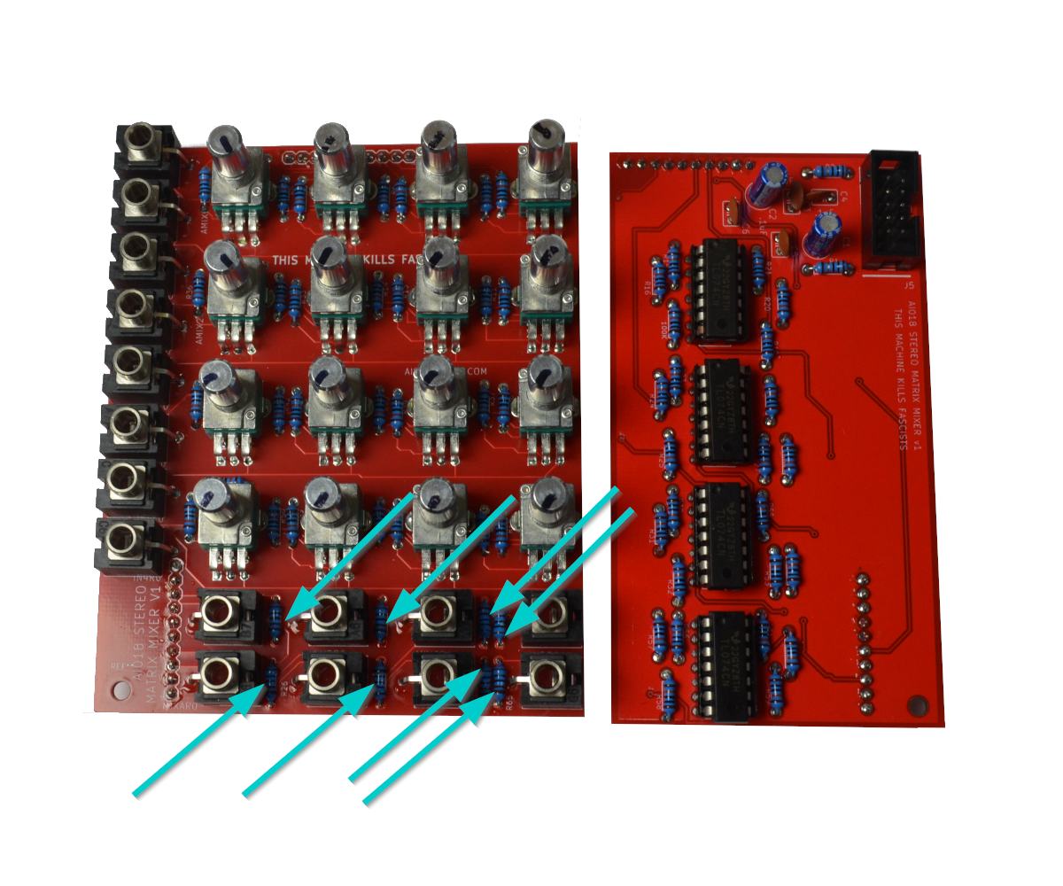
- Now solder the eight 1k resistors near the output jacks.
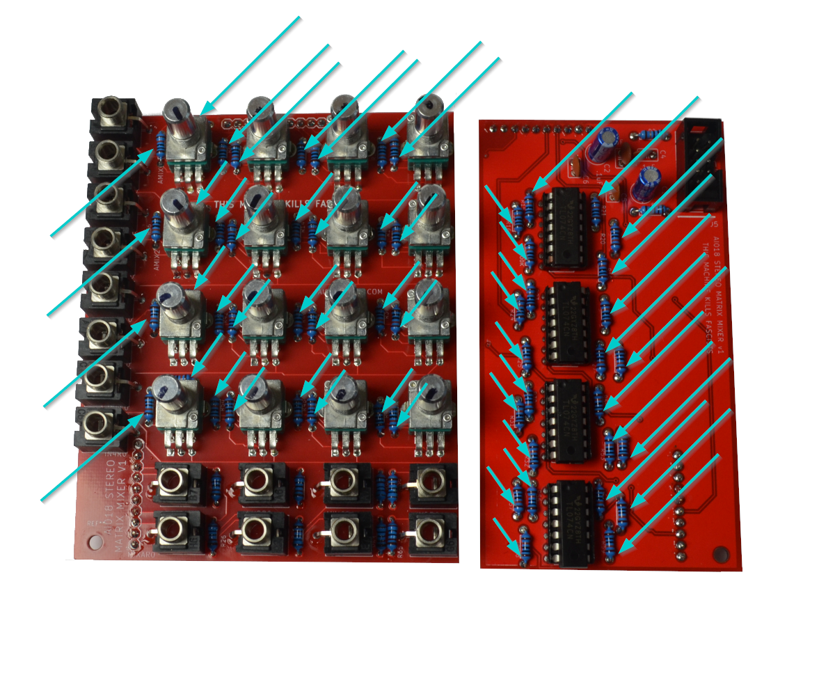
- Now solder the 56(!) 100K resistors. It’s a lot but after this it’s really easy.
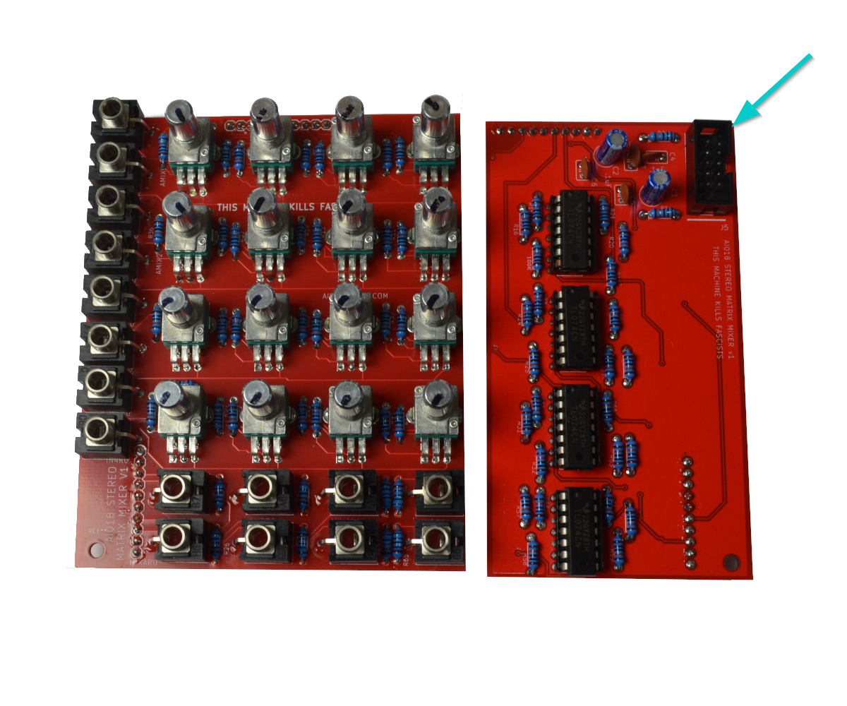
- Now solder the Power Header, which will take pressure off the caps we’re about to install.
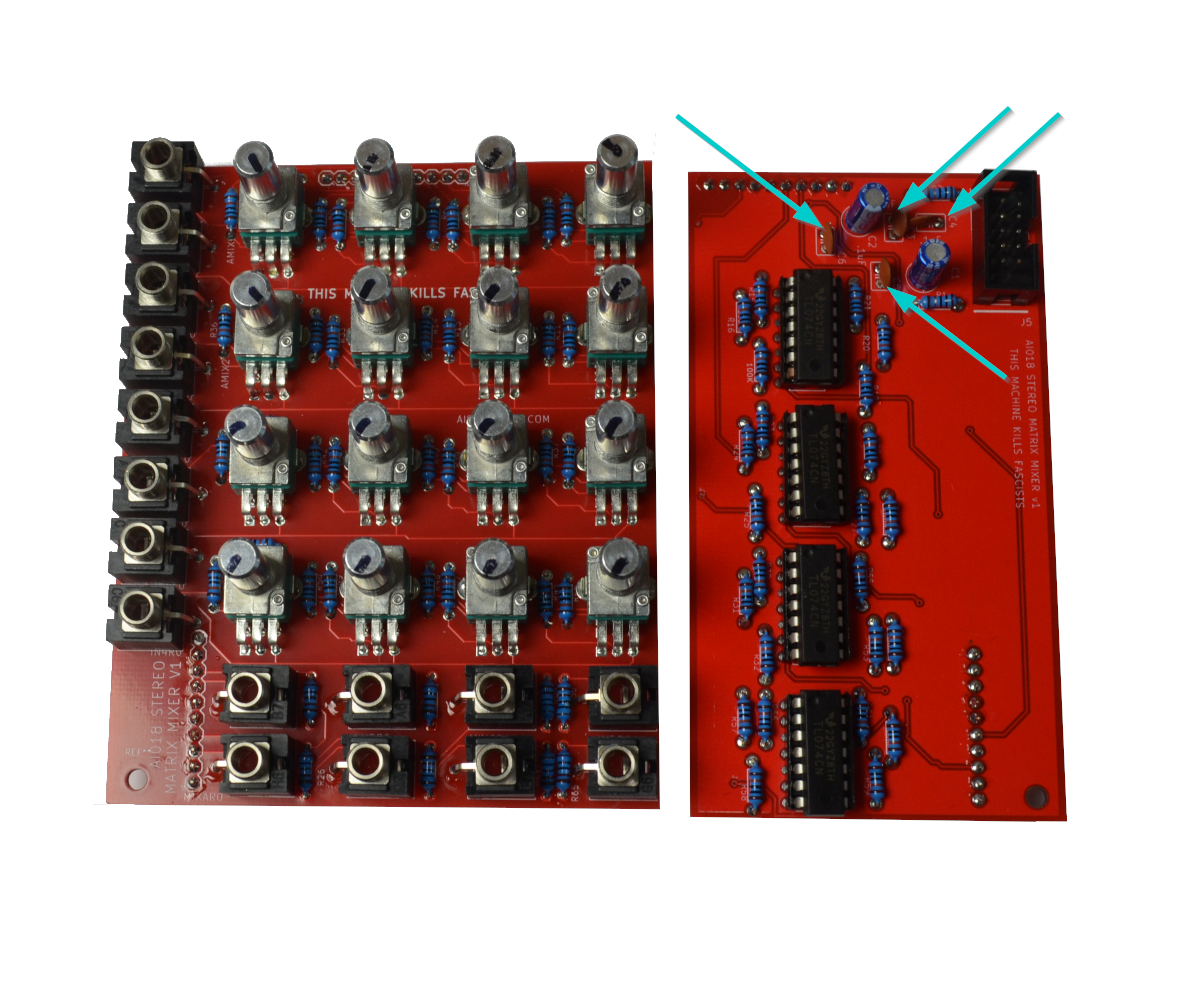
- Now solder the four .1uF caps that are part of the power filtering circuit.

- Now solder the four 14 pin sockets and then place in the TL074s. Make sure the “dot” on the ICs is pointed the right way.
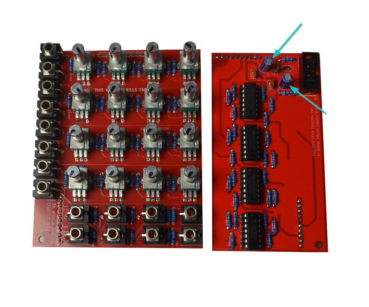
- Now solder the two 10uF Capacitors, minding the orientation.
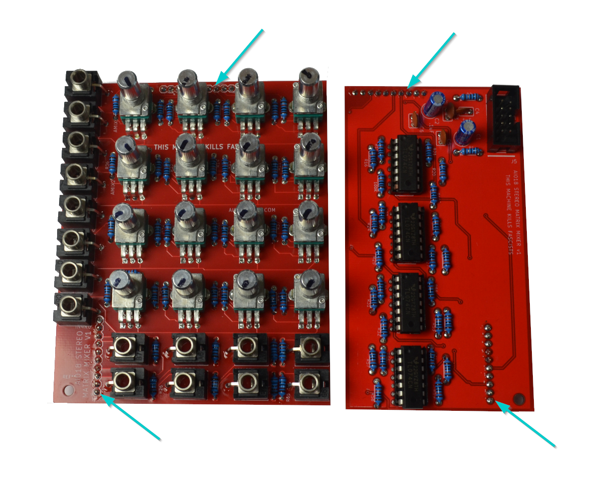
- Now solder the 2 sets of 10 pin sockets and plugs. In the end, the power header and jacks will face opposite. I like to always put the plug headers on the “bottom’ board, but you can do as you like.
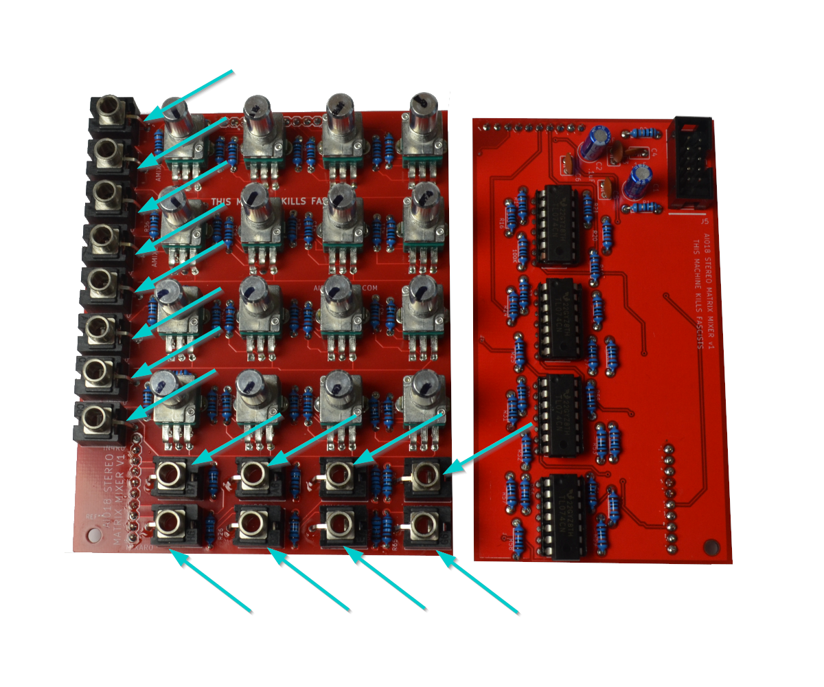
- Now solder the jacks. I like to lay the PCB flat and place in the jacks and then solder the ground lugs (the ones that stick out) from the top. Once those are in I turn the board over and solder/reflow all the jack pins.
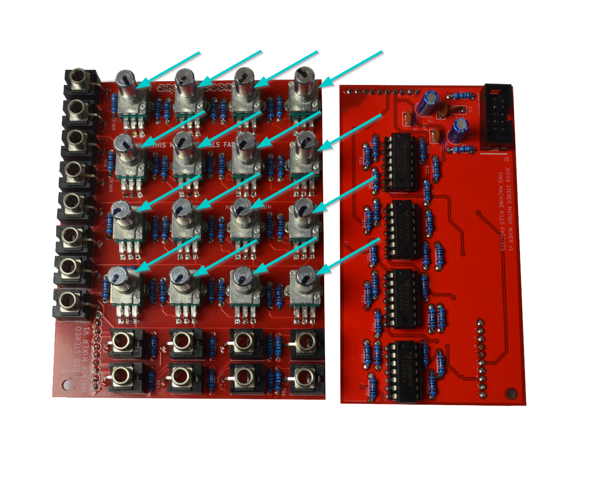
- Now solder in the 16 dual A100k Pots. I place them in the PCB and then put the panel on it. I’ll put on four nuts on the soldered jacks, and with the panel secure over the pots, turn the PCB and Panel over and solder the pots.
- Now We’re done! Perform a Continuity Test and power on if there are no shorts between +, -, and GND.
Congratulations!
Share your build on Facebook and Instagram!
If you are having any issues at all, please contact me at: https://aisynthesis.com/contact/.