DIY Eurorack Power Supply Build Guide
This is the build guide for the Eurorack Power Supply
Table of Contents
- Resources
- About the DIY Eurorack Power Supply
- Tools Needed
- BOM (Bill of Materials)
- Eurorack Power Supply Build Steps
1. Resources
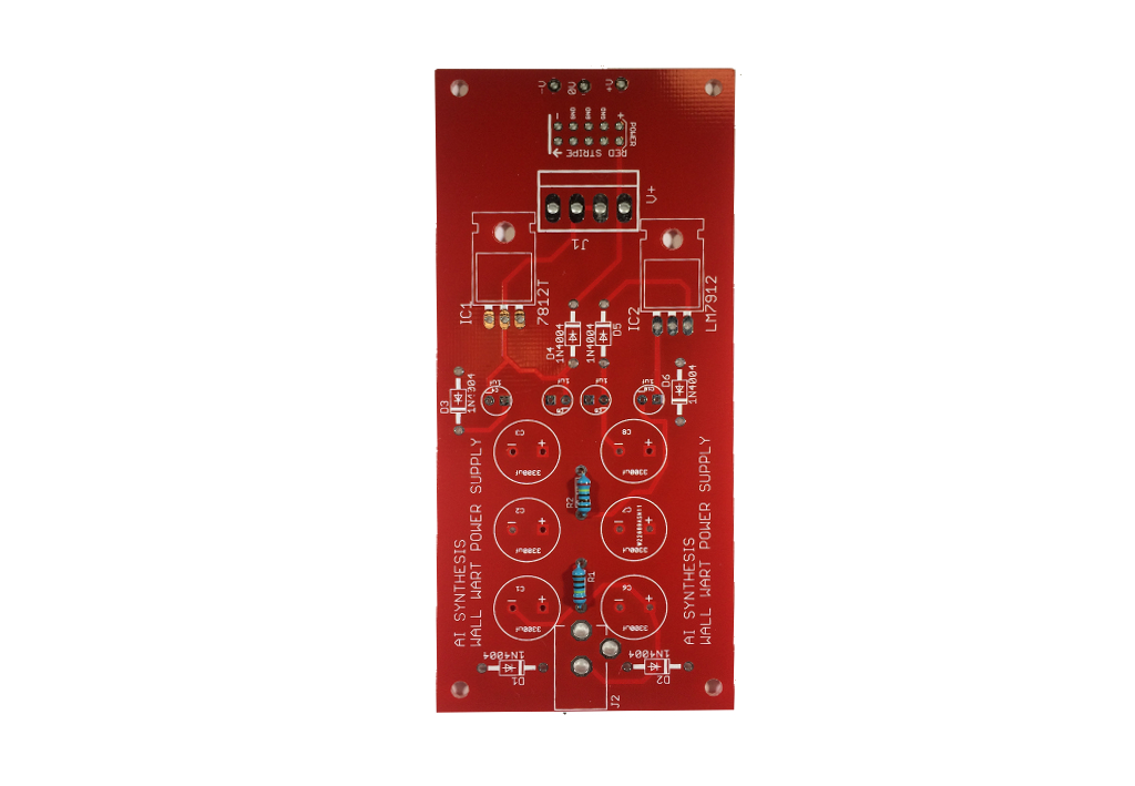
2. About the DIY Eurorack Power Supply
This is not a beginners module. If you haven't built anything before, stop now, and get the AI001 Multiple Eurorack Synthesizer Module. While not a difficult build per se, nearly ever component of the DIY Eurorack Power Supply is polarized, and must be "facing" the right direction on the PCB, or you will have exploding capacitors. Great care and attention are needed when building this module.
3. DIY Electronics Tools
- Soldering Iron: Cheap
or Nice
- Solder
- Soldering Tip Cleaner
- Micro Shears
- A Multi-Meter
- Safety Glasses
4. BOM
| Category | Part | Quantity |
|---|---|---|
| Capacitor | 3300uF | 6 |
| Capacitor, | 1uF Electrolytic Caps | 4 |
| Diode | 1N4004 | 6 |
| Hardware | 12V AC to AC(!) Wall Wart | 1 |
| Hardware | AC Jack | 1 |
| Regulator | LM7812 | 1 |
| Regulator | LM7912 | 1 |
| Resistor | 2.4K | 2 |
| Optional | 10 pin Euro Connector | 1 |
For +/- 15V supplies, make the following changes:
- Replace LM7812 with an LM7815
- Replace LM7912 with an L7915
- Use Heat Sinks with the regulators like these
- A 16V Wallwart instead of 12V
- Use the appropriate connector for your system
5. Build Steps
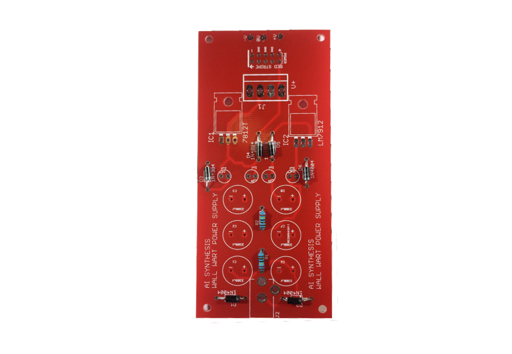
- As with most of our builds, you want to start building "low to high," meaning the "shorter" items first. In this case, that means the two 2.4K resistors at R1 and R2. It's very important to put these in before you install the 3300 caps, as it will be pretty tricky. Resistors aren't polarized, so it doesn't matter which way they go in. They are used to provide a load on the power supply when testing without any modules hooked up.
- Next we'll put in the six 1N4004 Diodes. It is critically important that you get the orientation correct on these. Match the stripes on the diodes as they are on the PCB. Two of these (D1 and 2) are there to cut the incoming AC voltage into two sources of DC voltage, and the other four are for safety - put em all in.
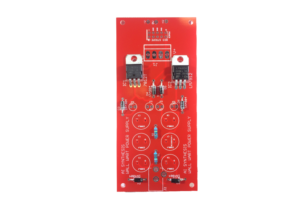
- Next put in the LM7912 and LM7812. DO NOT mix them up, or the circuit will blow. You don't need to provide a heatsink, but if you want to screw them into the PCB, it won't hurt anything.
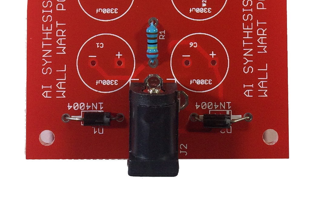
- Next put in the DC jack. It only goes in one way.
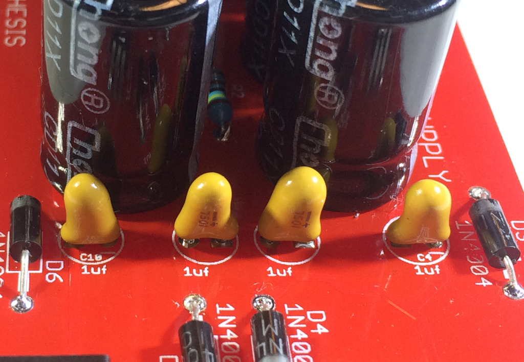
- At this time we can put in the four 1uF Electrolytic caps. These are polarized and need to go in the right way. The PCB has indicators for the - side, so make sure the positive leg is not in that hole. These are just here for safety as well, but you still need to make sure they are there and oriented correctly.Earlier versions used Tantalum capacitors, but Electrolytics are more reliable and easier to use.
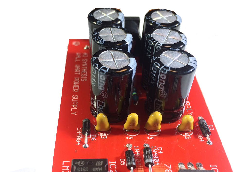
- With that done, you can put in the 6 big 3300uF caps. Make sure they are oriented the correct way. These are here to filter and clean up the bipolar power.
- Before we test with power, perform a quick continuity test.
- At this point it is a good time to test. Put on some safety goggles, and get your AC wallwart. The AC must be AC to AC, NOT Ac to DC. Plug in your AC wall-wart, then step back and wait a good 20-30 seconds. If nothing blows up, you can move on to testing.
- Hook the black lead of your multimeter to ground, and the red leg to +V, you should read around +12 V. Next move the red lead to the -V pad, you should read around -12V. It can be off by a little bit, as long as it is within a volt or so.
- Remove power and wire up the supply. In most cases, you'll be wiring the power supply to a bus-board PCB, but there are spots for a Eurorack and/or MOTM connector if you want to use this as a bench power supply.
- Share your build on Facebook and Instagram!
- If you want to learn more about managing power, read this Eurorack Power Guide!
- If you are having any issues at all, please contact us at: https://aisynthesis.com/contact/.