DIY Eurorack High Power Supply Build Guide
This is the build guide for the Eurorack High Power Supply Kit
Table of Contents
- Resources
- About the DIY Eurorack High Power Supply
- Tools Needed
- BOM (Bill of Materials)
- Build Steps
1. Resources
2. About the DIY Eurorack High Power Supply
This is a simple, easy to build way to distribute high power within a modular system. The Power Supply supplies a total of 5 AMPs (5,000mA) of +12v power, 2.5 Amps (2,500mA) of -12V power, Ground, and 400mA of +5V power to your modules via 12 shrouded connectors, and multiple chain points to other distribution boards. Three LEDs indicate status of the four power rails, and the Power Brick is included. The Eurorack High Power Supply uses super quiet DC to DC converters to turn one powerful DC brick into four reliable, quiet, power rails:
- +12V A: 2.5 Amps
- +12V B: 2.5 Amps
- -12v: 2.5 Amps
- +5V: 400mA
Headers 1-6 Draw their +12V from +12VA, and Headers 7-12 draw their +12V from +12VB.
3. DIY Electronics Tools
- Soldering Iron: Cheap
or Nice
- Solder
- Soldering Tip Cleaner
- Micro Shears
- A Multi-Meter
- Safety Glasses
4. BOM
,
| Category | Part | Quantity |
|---|---|---|
| Diode | RED LED | 4 |
| Hardware | DC Jack | 1 |
| Hardware | 2×8 pin Shrouded Header | 12 |
| Hardware (optional for heat shield) | Brass M3x10mm spacers, 2 flat m3 screws, 2 m3 screws | 2 each |
| Power Supply (Included in Kit and Built and Tested) | Chicony A135A022P 19.5V 6.92 Amp + tip supply | 1 |
| Regulator | URB2405LD-20WR3 | 1 |
| Regulator | URB2412LD-30WR3 | 3 |
| Resistor | 1K | 4 |
| Resistor | 470 Ohm | 1 |
5. Build Steps
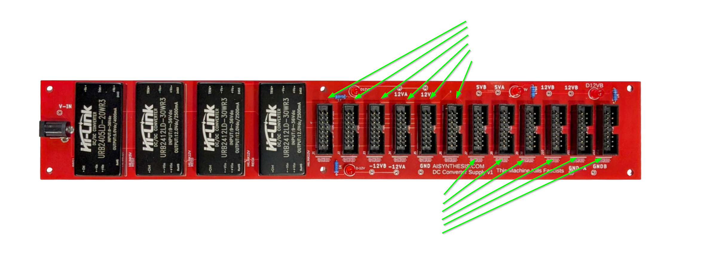
- Start with the shrouded headers. Ensure they match the orientation on the PCB. Watch the video for the method I use as these can be tricky. I like to get one pad soldered, and then move on to the next header, soldering them all afterwards.
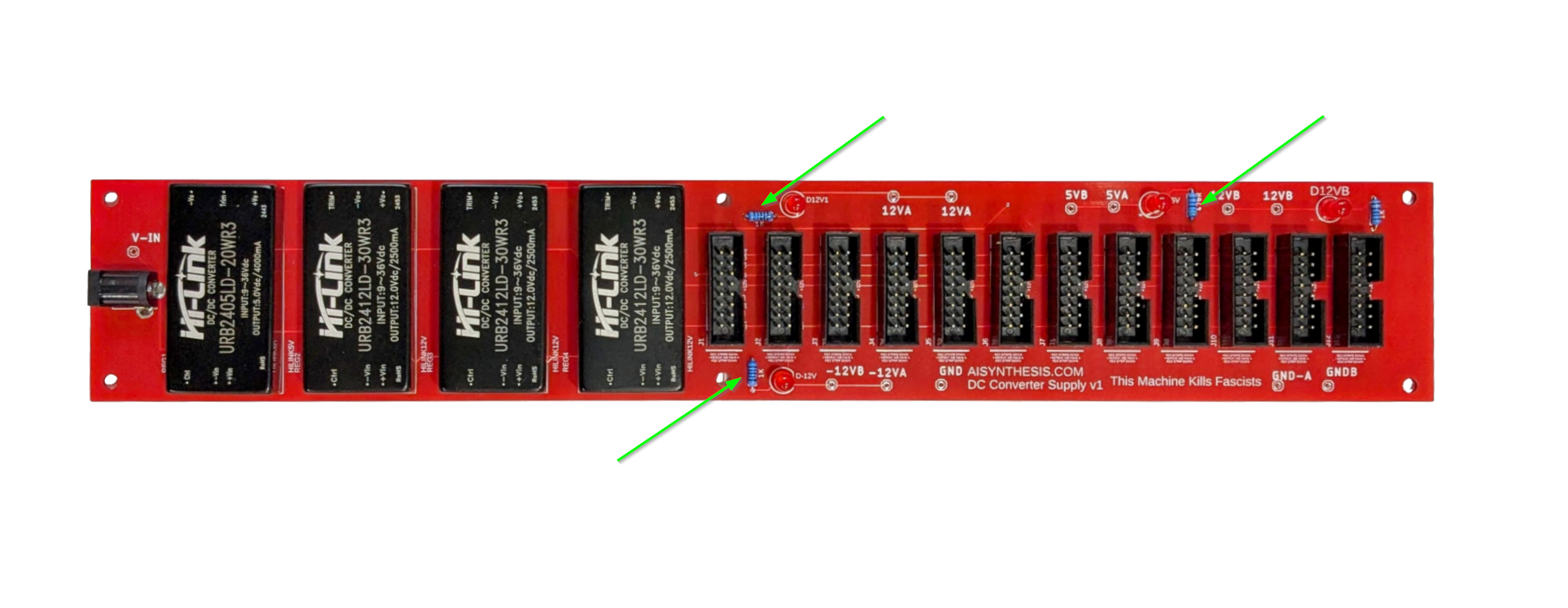
- Next we’ll put in the three 1k Resistors.
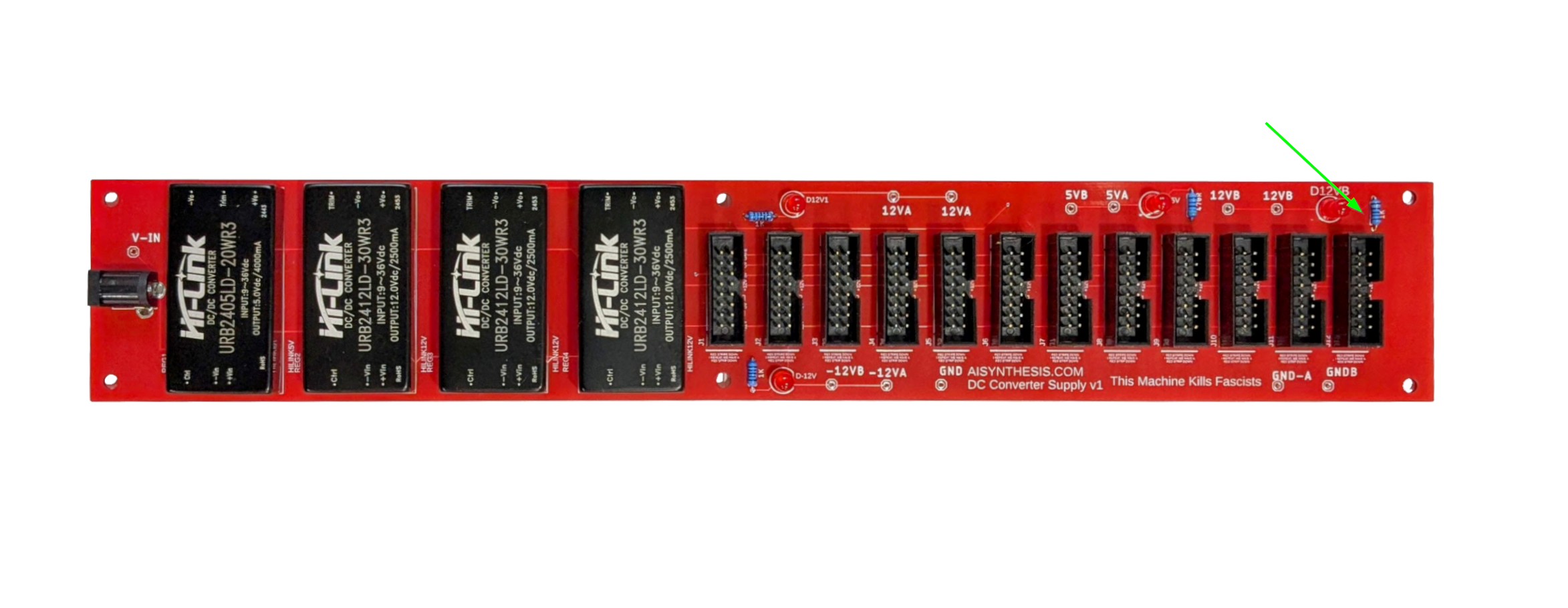
- Now move on to the single 470 Ohm resistor.
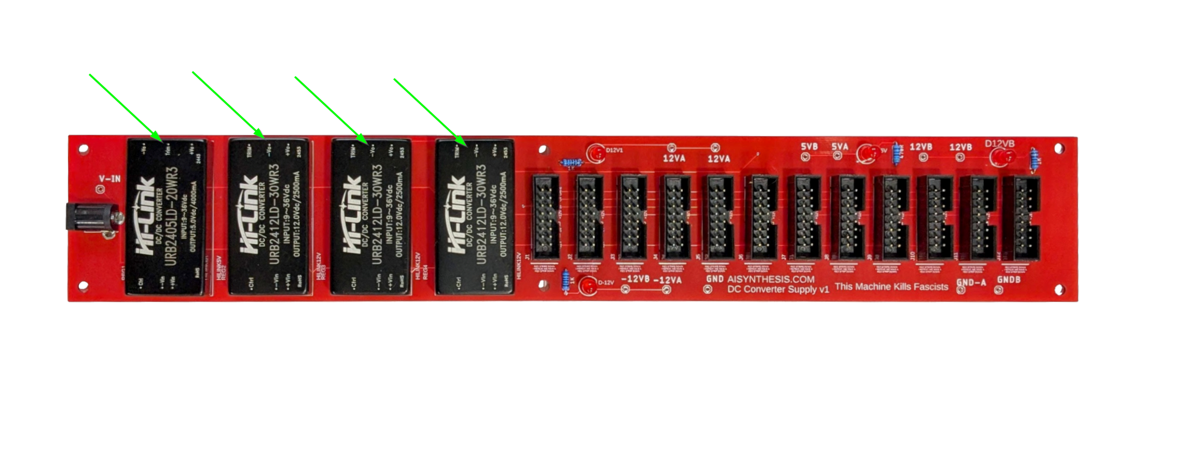
- Next, going from left to righ, solder the four DC-DC converters, starting with the 5V converter on the left. They only go in one way
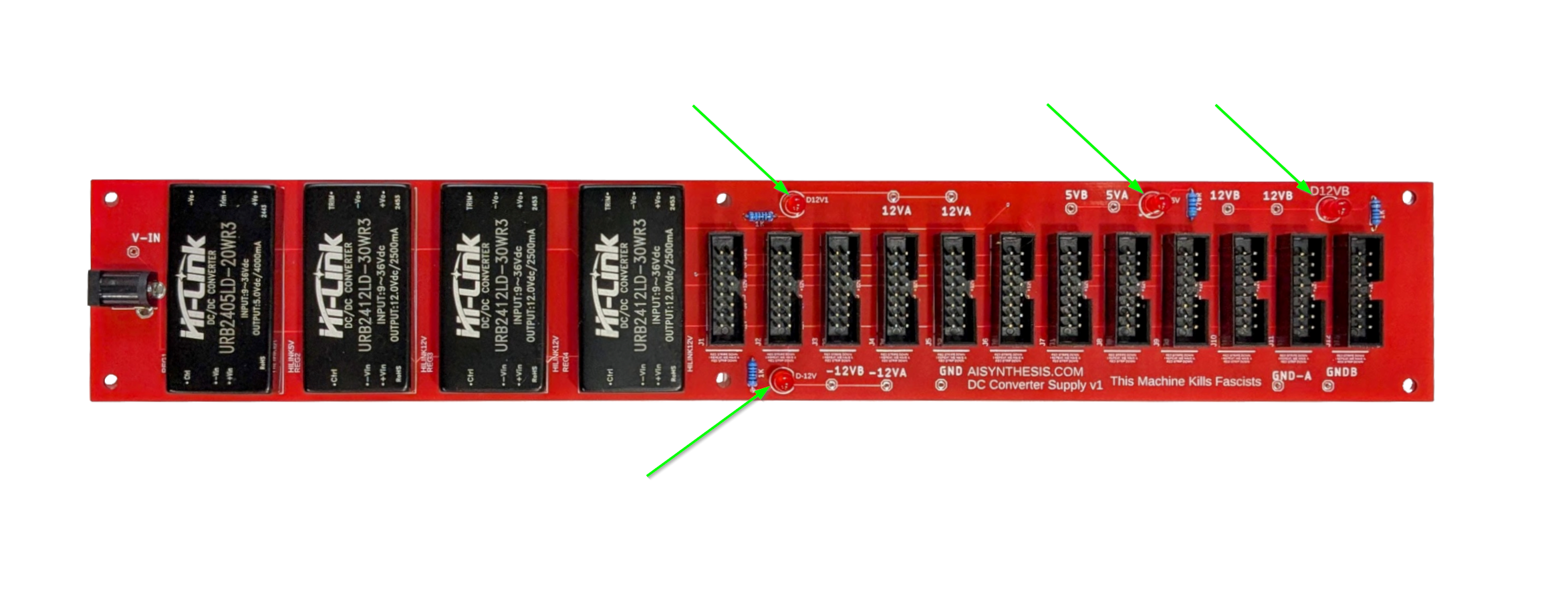
- Next put in the LEDs. These are optional, but light up in correspondence with the +12V, -12V, and +5V rails. Be sure to mind the polarity of the LEDs. The longer leg of the LED marks the “round” side of the LED.
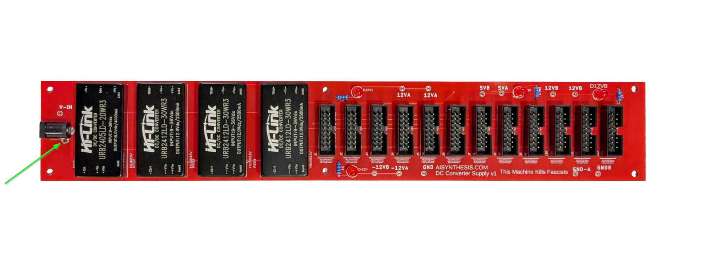
- Now solder the DC input Jack. This will deliver the DC power to all the converters.
- The converters get quite hot (120 degrees). The optional heat guard can be installed by using two 10mm spacers and provided M3 screws.
- Before we test with power, perform a quick continuity test. See the above or the build guide video. Ensure there is no continuity between Ground, +12v, +5v, and -12V and each other.
- If there is no continuity, then it is a good time to test. Put on some safety goggles, and get your power supply and connect the two.
- All four LEDs should light.
- Hook the black lead of your multimeter to ground, and the red leg to +12V, you should read around +12 V. Next move the red lead to the -V pad, you should read around -12V. Then move the red lead to +5V, it should read about 5V. It can be off by a little bit, as long as it is within a volt or so.
- Share your build on Facebook and Instagram!
- If you want to learn more about managing power, read this Eurorack Power Guide!
- If you are having any issues at all, please contact us at: https://aisynthesis.com/contact/.