Passive Filters
These Passive Filter PCBs allow for the easy creation of Passive Low Pass and Passive High Pass Filters.
3,00 €
Product Details
These Passive Filter PCBs allow for the easy creation of Passive Low Pass and Passive Hight Pass Filters.
These Passive Filters are "RC" filter circuits, composed of a resistor and a capacitor.
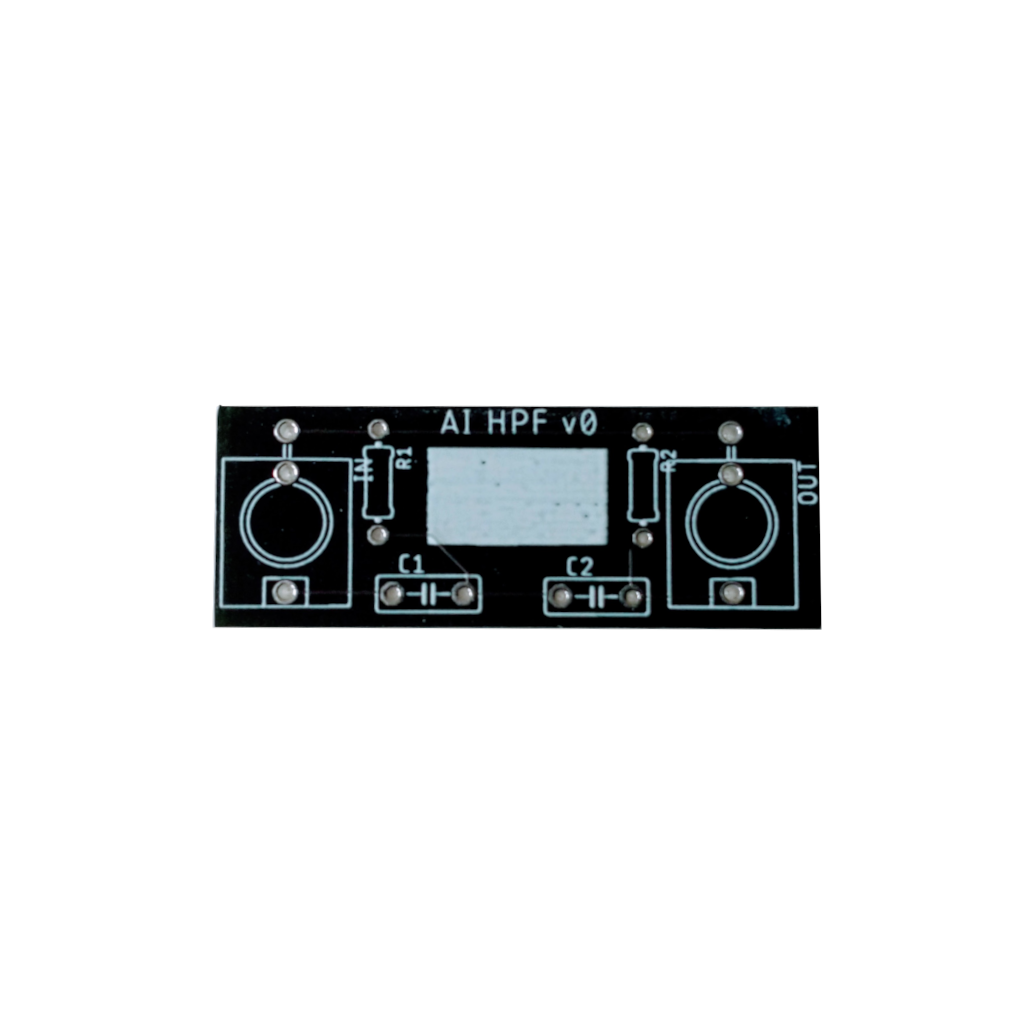
Passive Hi Pass Filters:
When a capacitor is placed in series with the signal and a resistor is placed in parallel, a high pass filter is created. Because capacitors offers very high resistance to low frequency signals, when placed in series with a signal, they block low-frequency signals from the output, but high-frequency signals are able to go through unimpeded. Use a high quality capacitor (film or better since audio will be passing through them). Additional pads are offered for your experimentation with second order filters, etc.... To build a Passive High Pass Filter:
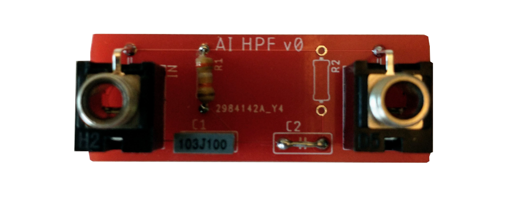
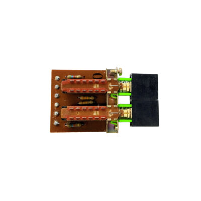
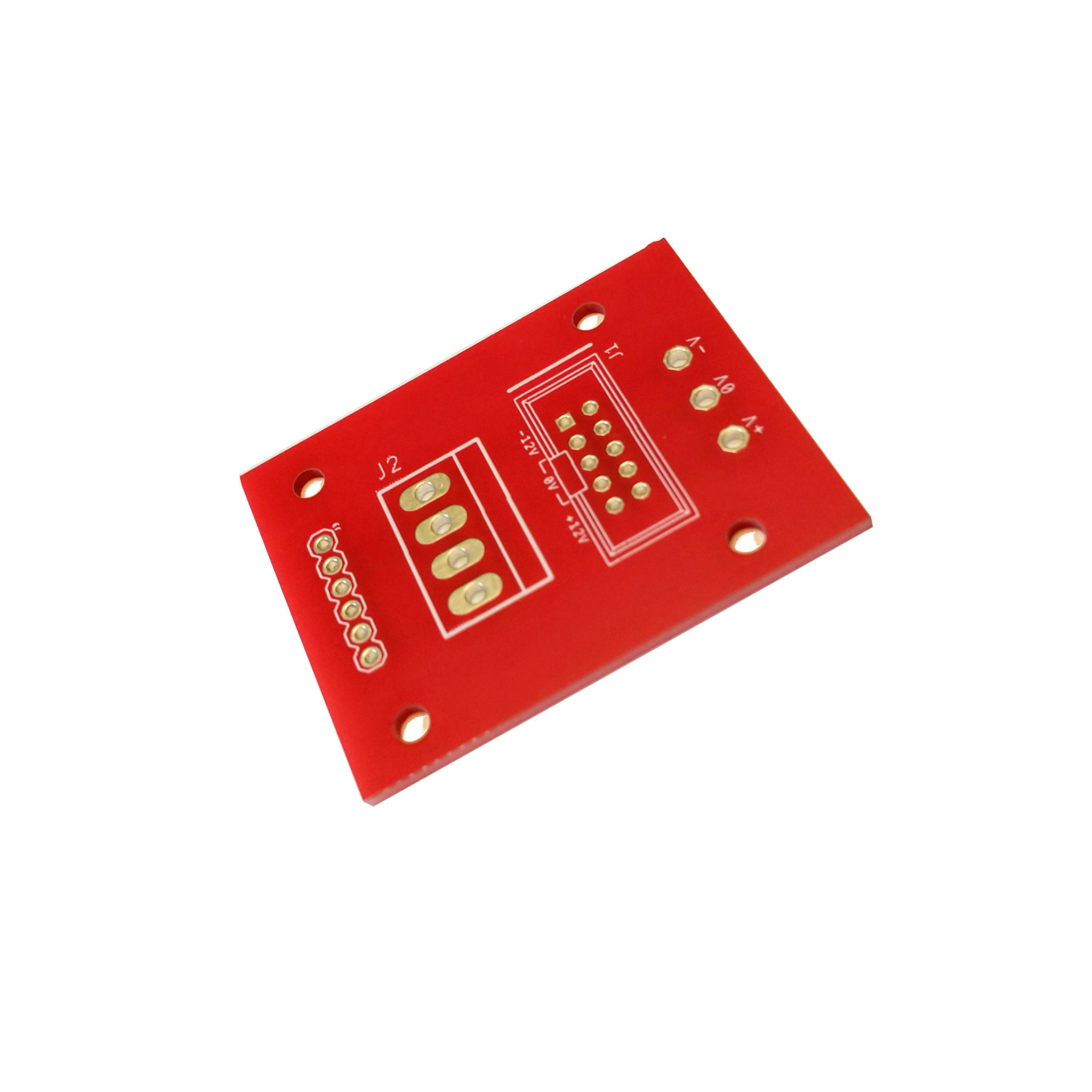
These Red PCBs are prototypes - the "real" ones are Black.
- Use this guide to select a cap and resistor for the frequency desired. I like to put in the frequency and a 10nF cap and let it choose a resistor for me. DO NOT ask me to do math for you. What kind of monster are you!?!?! Note that the filter slope is about -3db per octave, so if you want to filter out 100Hz from your bass to make room for your kick, you might want to enter 130Hz or something.
- Solder the resistor value it gives in R1 and use extra resistor wire to form a bridge across C2.
- Solder the cap value you entered in C1.
- Solder two jacks - you are done. You can write the Frequency you set in the white space on the PCB.
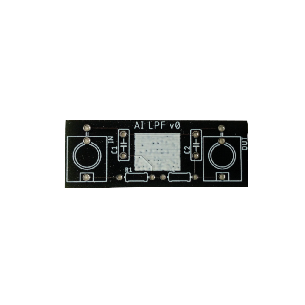
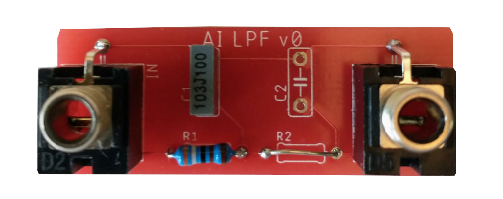
Passive Low Pass Filters:
When a resistor is placed in series with the signal and a capacitor is placed in parallel, a low pass filter is created. Because capacitors offers very high resistance to low frequency signals, the low frequencies pass through to the output and high frequencies go to ground. Additional pads are offered for your experimentation with second order filters, etc....
To build a Passive Low Pass Filter:
- Use this guide to select a cap and resistor for the frequency desired. I like to put in the frequency desired and a 10nF cap and let it choose a resistor for me. DO NOT ask me to do math for you. What kind of monster are you!?!?! Note that the filter slope is about -3db per octave, so if you want to filter out 10kHz from your bass to make room for other high frequency content in your mix, you might want to enter 9kHz or something.
- Solder the resistor value it gives in R1 and use extra resistor wire to form a bridge across R2.
- Solder the cap value you entered in C1.
- Solder two jacks - you are done. You can write the Frequency you set in the white space on the PCB.
Furthering your education:
You can use these same PCBs to make second order filters. A second order filter will have a 6db cutoff as opposed to a 3db cutoff. I encourage you to google and learn more about those circuits. This is a great guide, but it does have a lot of math.
Only logged in customers who have purchased this product may leave a review.
Related products
Passive Filters
These Passive Filter PCBs allow for the easy creation of Passive Low Pass and Passive High Pass Filters.
3,00 €
Product Details
These Passive Filter PCBs allow for the easy creation of Passive Low Pass and Passive Hight Pass Filters.
These Passive Filters are "RC" filter circuits, composed of a resistor and a capacitor.
Passive Hi Pass Filters:
When a capacitor is placed in series with the signal and a resistor is placed in parallel, a high pass filter is created. Because capacitors offers very high resistance to low frequency signals, when placed in series with a signal, they block low-frequency signals from the output, but high-frequency signals are able to go through unimpeded. Use a high quality capacitor (film or better since audio will be passing through them). Additional pads are offered for your experimentation with second order filters, etc.... To build a Passive High Pass Filter:
These Red PCBs are prototypes - the "real" ones are Black.
- Use this guide to select a cap and resistor for the frequency desired. I like to put in the frequency and a 10nF cap and let it choose a resistor for me. DO NOT ask me to do math for you. What kind of monster are you!?!?! Note that the filter slope is about -3db per octave, so if you want to filter out 100Hz from your bass to make room for your kick, you might want to enter 130Hz or something.
- Solder the resistor value it gives in R1 and use extra resistor wire to form a bridge across C2.
- Solder the cap value you entered in C1.
- Solder two jacks - you are done. You can write the Frequency you set in the white space on the PCB.
Passive Low Pass Filters:
When a resistor is placed in series with the signal and a capacitor is placed in parallel, a low pass filter is created. Because capacitors offers very high resistance to low frequency signals, the low frequencies pass through to the output and high frequencies go to ground. Additional pads are offered for your experimentation with second order filters, etc....
To build a Passive Low Pass Filter:
- Use this guide to select a cap and resistor for the frequency desired. I like to put in the frequency desired and a 10nF cap and let it choose a resistor for me. DO NOT ask me to do math for you. What kind of monster are you!?!?! Note that the filter slope is about -3db per octave, so if you want to filter out 10kHz from your bass to make room for other high frequency content in your mix, you might want to enter 9kHz or something.
- Solder the resistor value it gives in R1 and use extra resistor wire to form a bridge across R2.
- Solder the cap value you entered in C1.
- Solder two jacks - you are done. You can write the Frequency you set in the white space on the PCB.
Furthering your education:
You can use these same PCBs to make second order filters. A second order filter will have a 6db cutoff as opposed to a 3db cutoff. I encourage you to google and learn more about those circuits. This is a great guide, but it does have a lot of math.
Reviews
Only logged in customers who have purchased this product may leave a review.
Reviews