
AI003 Eurorack ADSR DIY Synth Kit Build Guide
This is the build guide for the AI003 Looping ADSR Envelope Generator DIY Kit
Table of Contents
- Resources
- About the Eurorack ADSR DIY Synth Kit
- Tools Needed
- BOM (Bill of Materials)
- Build Guide
1. Resources
2. About the Eurorack ADSR DIY Kit
If you are new to DIY electronics, this is the third module you should build. The first module, the AI001 Multiple Eurorack Synthesizer Module is ideal for beginners, as it teaches how to solder, and familiarizes the builder with the concepts of signal and ground. The second module, the AI002 DIY Synthesizer Mixer module familiarizes you with pots, ICs, and Eurorack power. If you successfully built those, this Eurorack ADSR DIY synth kit is the perfect bridge between beginner and medium to difficult modules. It has two ICs, and a fair number of steps, but can still be built in a single sitting. The Looping ADSR Envelope Generator DIY Kit is an ADSR Envelope Generator with the ability to also function as a variable wave LFO. This module can be used to feed control voltage to a filter or vca to modulate, for instance the volume of an sound source, or the cutoff of a filter.
3. Tools Needed
- Soldering Iron: Cheap
or Nice
- Solder
- Soldering Tip Cleaner
- Diagonal Cutters
- Micro Shears
- Precision Screwdriver Set
4. BOM
| Category | Part | Quantity |
|---|---|---|
| Capacitor (Electrolytic) | 10uF | 3 |
| Capacitor | .1uF | 6 |
| Diode | 1N4148 | 10 |
| Hardware | Female 8 Pin Header | 1 |
| Hardware | Male 8 Pin Header | 1 |
| Hardware | Female 6 Pin Header | 1 |
| Hardware | Male 6 Pin Header | 1 |
| Hardware | 2x5 Pin Header | 1 |
| Hardware | 14-Pin IC Socket | 1 |
| Hardware | 8-Pin IC Socket | 1 |
| Hardware | Jack | 3 |
| LED | Red LED with optional 5mm Spacer | 1 |
| IC | TL074 | 1 |
| IC | TL072 | 1 |
| Potentiometer | 9mm Alpha Potentiometer A500K | 1 |
| Potentiometer | 9mm Alpha Potentiometer B10K | 1 |
| Potentiometer | 9mm Alpha Potentiometer A1M | 2 |
| Resistor | 10R OR 1N5817 Diode | 2 |
| Resistor | 10K | 8 |
| Resistor | 33K | 1 |
| Resistor | 390K | 1 |
| Resistor | 4.7K | 1 |
| Resistor | 100K | 2 |
| Resistor | 15K | 1 |
| Resistor | 1K | 4 |
| Resistor | 1M | 2 |
| Resistor | 5.1M | 2 |
| Resistor | 100 Ohm | 1 |
| Switch | DPDT Switch and optional cap | 1 |
| Switch | Momentary Switch Red or Black | 1 |
| Transistor | 2N3906 | 1 |
| Optional Mounting Hardware | 8mm x3mm PCB Spacers | 2 |
| Power Cable | Eurorack Power Cable | 1 |
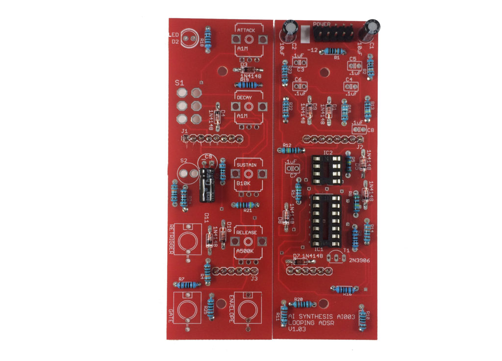
5. Build Guide
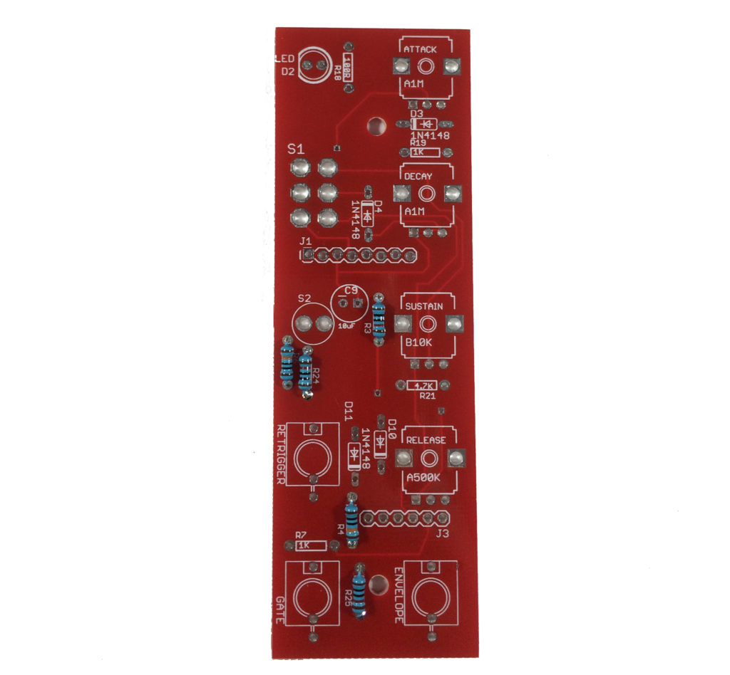
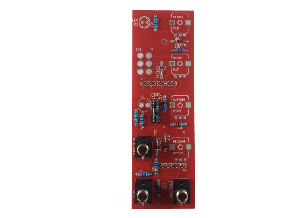
- First, gather your parts together, and snap the two PCBs in half in order to make two PCBs.
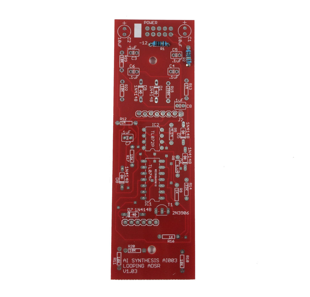
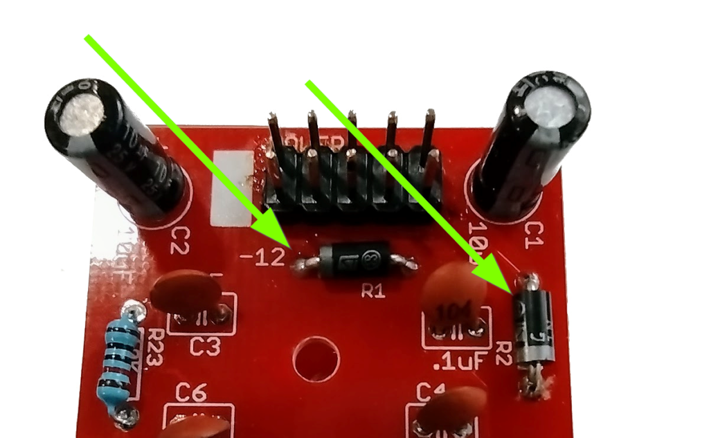
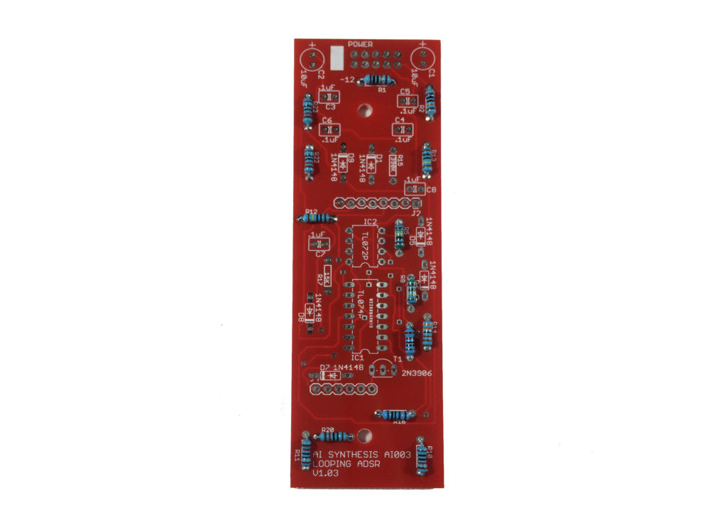
- In general with DIY electronics, we want to build “low to high.” “Low to High” means soldering items in reverse order of height, as it is easier to manipulate smaller items when there aren’t taller things to get in the way. In this case, it means starting with the resistors. Start by soldering the two 10R resistors OR 1N5817 Diodes at R1 and R2. Your kit may have either part, and both are fine. The kits are transitioning to using 1N5817 Diodes instead of 10 Ohm resistors for further reverse power protection. The 10 Ohm resistors are not polarized and have no orientation. The 1n5817 Diodes must be put in the correct orientation, shown below. When I re-order PCBs they will have the orientation on the PCB. I didn’t want to throw out a bunch of otherwise good PCBs.
- After that move on to the 8 10K resistors. There are 3 on the "top" board and 5 on the bottom.
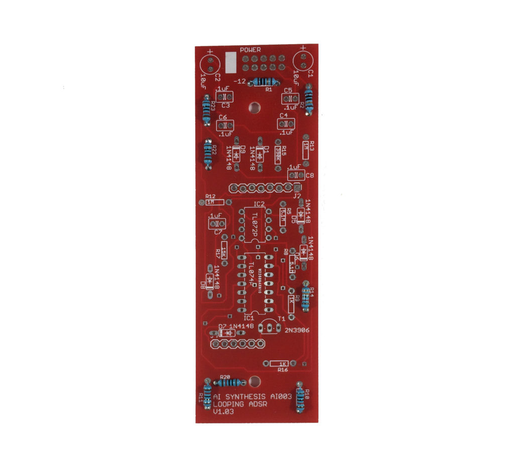
- There is one 33K resistor at R14 on the bottom board.
- There are two 100k resistors on the top board.
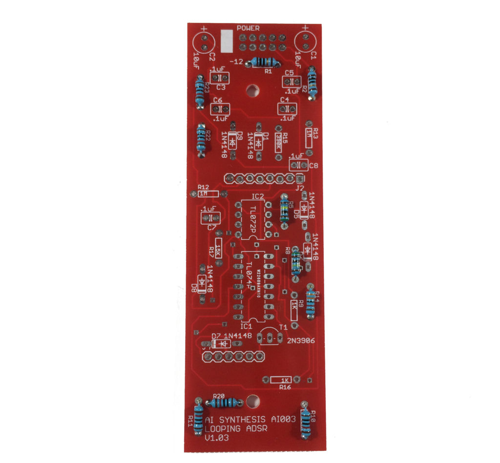
- There are two 5.1M resistors on the bottom board
- There are four 1K resistors, two on the top board, and two on the bottom board.
- There are two 1M resistors on the bottom board.
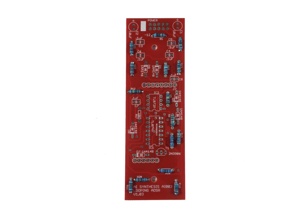
- There is one 390K resistor on the bottom.
- There is one 15K resistor on the bottom board as well.
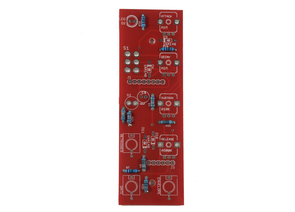
- There is one 100R (R18) Resistor on top board next to the LED, and a 4.7K resistor (R21) between the Sustain and Release pots.

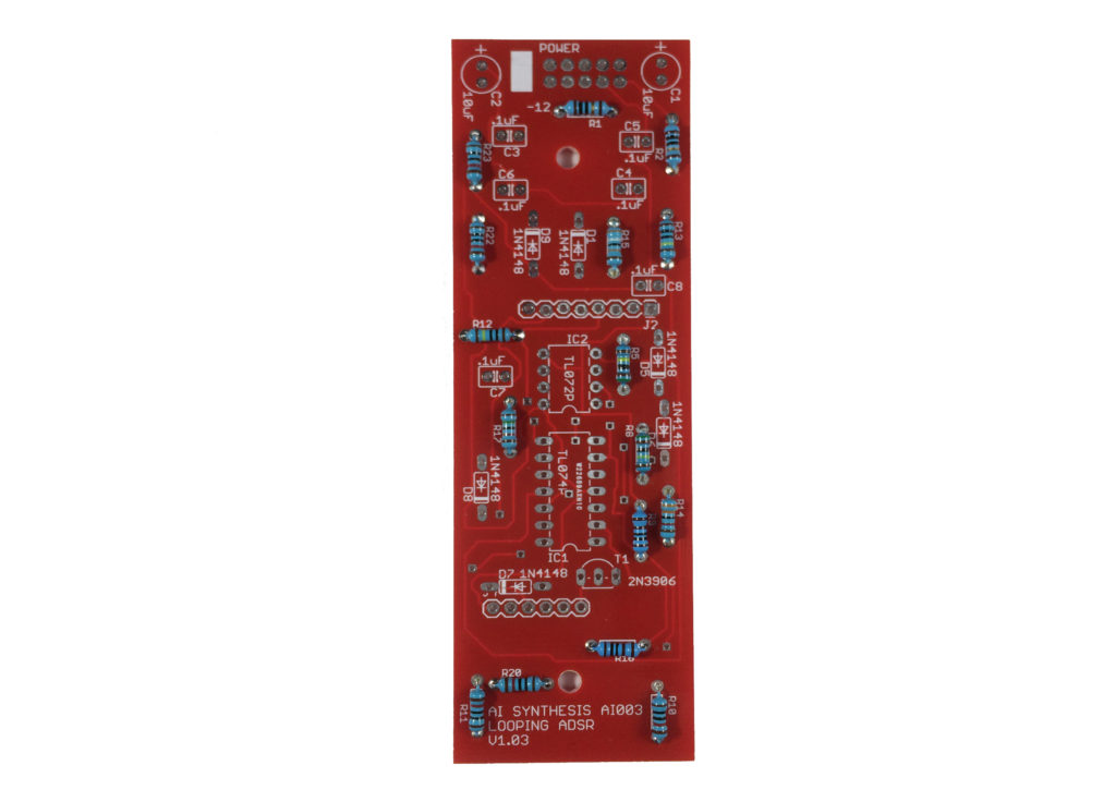
- There are 10 1N4148 Diodes. These diodes are polarized, and you will need to ensure that the black line on the diode is aligned with the white line on the PCB silkscreen. These are switching diodes.
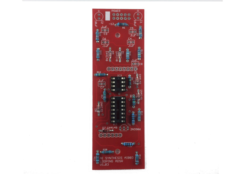
- Add the 8 and 14 Pin IC sockets. You could solder the two ICs to the board directly, but it is prudent to use a header, as desoldering an IC can be a real pain. Be mindful of the orientation. Each of the sockets have a small notch in them to indicate orientation. The notches on the sockets should match the orientation of the silk screens on the PCB. Obviously, the sockets themselves are just connectors, and it is the IC chips that have orientation, but it is good to have all of the orientations matching.
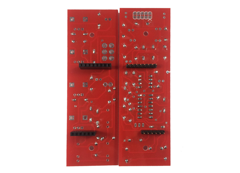
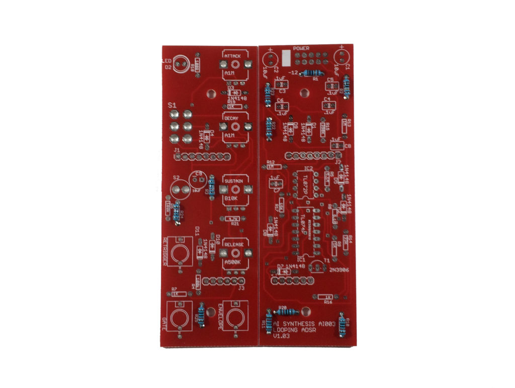
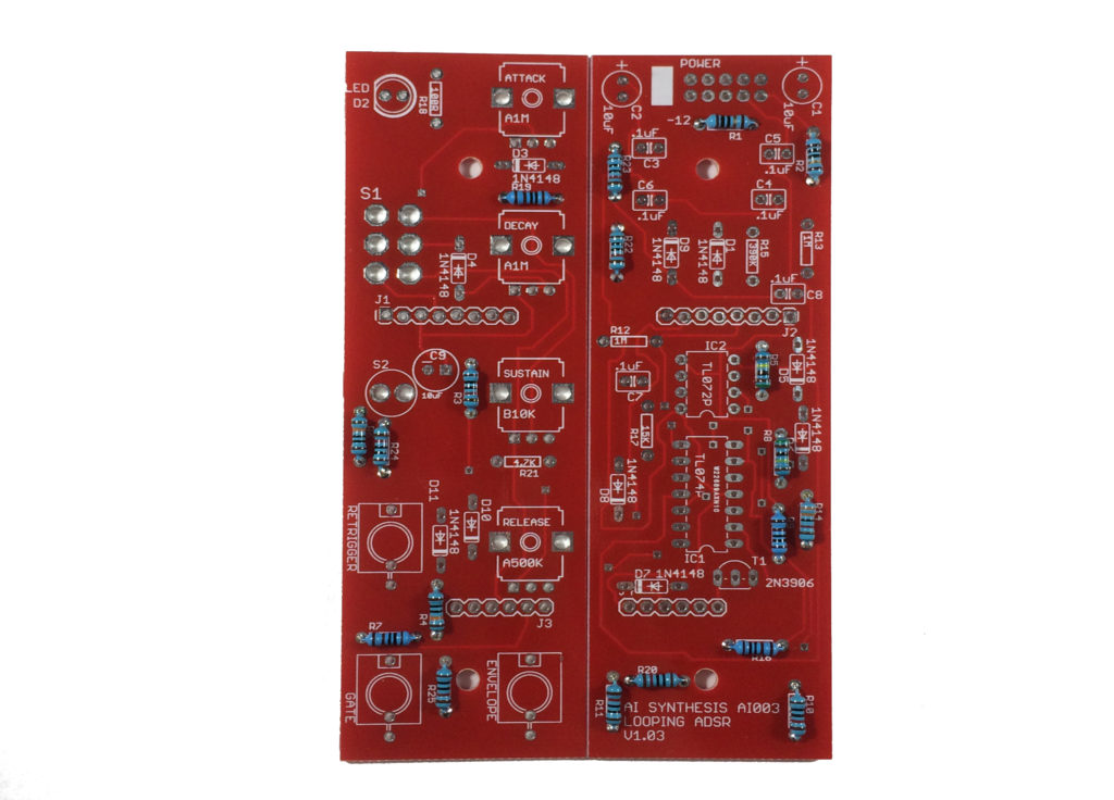
- At this point it is good to add the headers J1-J4, as other components will soon get in the way. These headers will connect the two boards and transmit signals between the two. It doesn't matter which side is the "male" or "female" half, so long as one goes into the other. I find that the easiest method is to put the headers together and put the boards together, and then solder the headers in with the boards put together. Otherwise they often end up a bit skewed. Be sure to solder them to the sides shown above, so that the "knob-end" of the PCB and the "power end" of the PCB end up on the right sides.
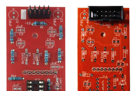
- Now we'll add the power header. You can just insert the dual 5 pin header, turn the board upside-down, and then solder it in, with gravity making it straight. If you are using a shrouded header, the notch should be on the bottom. When in doubt, insert your power cable, you want the red stripe on the cable to line up with the white stripe on the PCB.
- Next we'll add the three 10uF Capacitors. On the panel side, the 10uF cap should be bent 90 degrees as shown before soldering it in. This way it won't obstruct the panel when it is time to put it on. We're adding them at this stage because, on the bottom board, when you are soldering in the next components, the caps will keep some of the shorter caps from being bent. These electrolytic capacitors are polarized. Each capacitor will have a stripe on one side. This stripe indicated the negative side. Ensure that the capacitor is correctly aligned with the positive / negative symbols on the PCB.
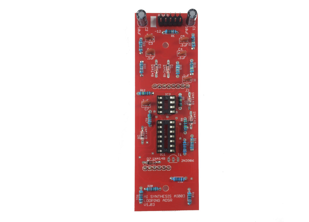
- Speaking of the smaller caps. There are 6 .1uF Capacitors on the bottom board.

- The last part on the bottom board is the 2N3906 Transistor. Ensure that it is inserted matching the silkscreen on the PCB, with the round face facing the IC. That's it for the bottom board.
- Now for the jacks. There are three switched mono jacks on the top panel. They don't unsolder that easily, so it's best to get them right the first time. Luckily, it's easy to do: With the board facing up, insert the jack, and while it is laying flush, lightly solder the ground lug (that's the lug sticking out of the jack on the top side). Then you can turn the board over and do the other two lugs (and re-flow the ground lug) assured that the jacks will be nice and flat against the board.
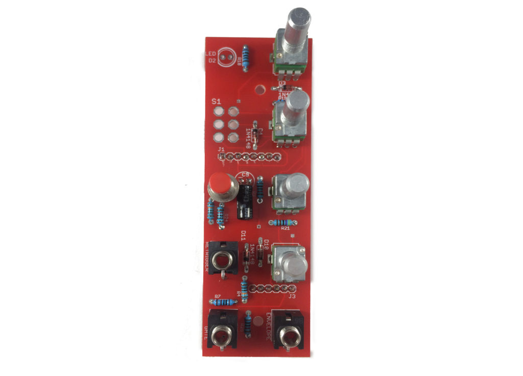
- Insert the momentary switch with the red cap, the two A1M (might say A105) potentiometers, the B10k (might say B103) potentiometer, and the A500K (might say A504) potentiometer. When you turn the board over to solder the connections the momentary switch will balance the board with the potentiometers.
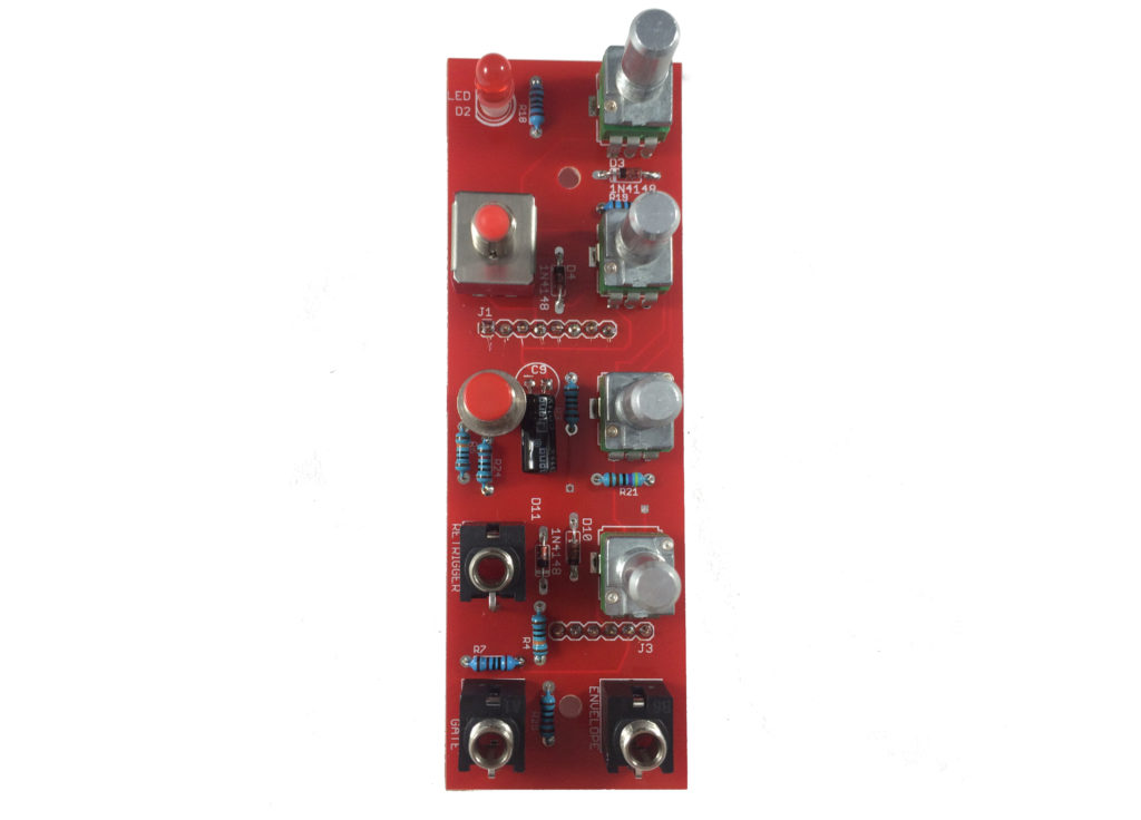
- Finally add the DPDT Switch (with optional red cap) and the LED with it's 5mm spacer. You can go without the spacer if you like, but it is the perfect distance for getting the LED just over flush with the panel. The easiest way to get the fit just right is to place the panel over the top panel before you solder these two final components. Use the panel to align the parts correctly, and then solder the parts in.
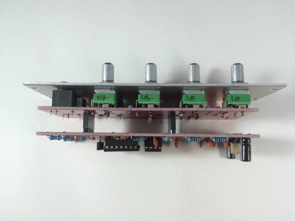
- Now fit the two boards together. You are ready to test!
- Before you finally peel of the panels protective layer and put on the panel, let’s test the module. Without applying power, ensure that there is no continuity between the positive, ground, and negative voltage power pins using a digital multi-meter. You test by connecting one test lead of the multimeter to ground and the other to positive voltage. There should be no continuity.
Next test by connecting one test lead of the multimeter to ground and the other to negative voltage. There should be no continuity.
Next test by connecting one test lead of the multimeter to positive and the other to negative voltage. There should be no continuity. Assuming there is no continuity there, you are good to apply power. Eurorack, tragically, has no universal power connector format. This has resulted in far too many blown up modules. AI Synthesis modules follow the most common format, in which there is a white stripe next to the negative end of the power connector, and this is typically where the red stripe of the power cable should be aligned, but check your power supply for details. I like to give a freshly powered module a few seconds to ensure that nothing smokes and there is no danger of fire. This is why it is nice to have a bench power supply to test a module apart from your Eurorack system. If everything looks good, you are good to test prior to applying the panel and finishing up. - The easiest way to test is to put the switch into Loop mode, and power on. With the Attack and Decay down, you will have short LED pulses, with them up, they will be long. If it's working, time to rack it up!
- Share your build on Facebook and Instagram!
- If you are having any issues at all, please contact me at: https://aisynthesis.com/contact/.