AI002 DIY Synthesizer Mixer Module Build Guide
This is the build guide for the AI002 Mixer
Table of Contents
- Resources
- About the DIY Synthesizer Mixer Module
- Tools Needed
- BOM (Bill of Materials)
- Build Steps
1. Resources
2. About the Mixer
 If you are new to DIY electronics, this is the second module you should build. The first module, the AI001 Multiple Eurorack Synthesizer Module is ideal for beginners, as it teaches how to solder, and familiarizes the builder with the concepts of signal and ground, the basis of electronics. If you successfully built the multiple, this DIY Synthesizer Mixer Module kit will familiarize you with the other components you’ll be seeing: resistors, capacitors, ICs, and power.
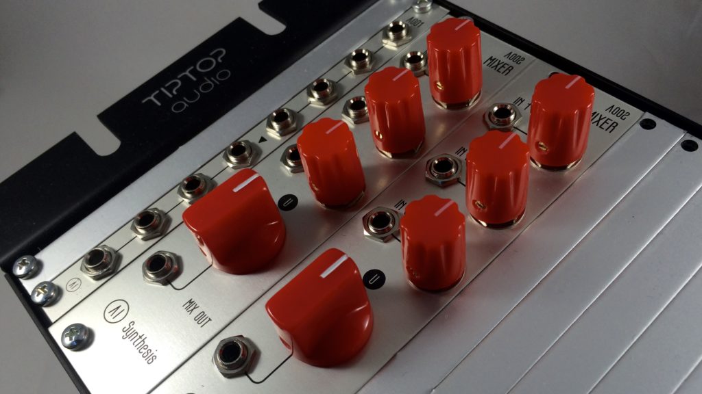
The AI002 DIY Mixer Kit is an active signal mixer. This DIY Synthesizer Mixer Module can operate on +/- 12 or +/- 15 volts with no adjustments. This mixer is a DC mixer, meaning it can be used to combine audio and/or cv signals. ThisDIY Synthesizer Mixer Module can be used to feed multiple oscillators into a filter, or to feed multiple cv sources into, for instance, the cv in of a filter.
The circuit itself is quite simple and uses two Operational amplifiers in a unity gain inverting configuration. The P1-3 pots attenuate the input signal then feed it through 100k resistors for protection into the first op-amp, which mixes the signal. The 4th pot controls feedback into the op-amp, in order to control the master output of the mixed signal. The output is then inverted. The second op-amp is a simple inverter, that then provides a non-inverted output. In audio mixing, an inverted signal is essentially irrelevant, but for CV, you typically want a non-inverted signal. Otherwise, your envelope will be inverted.
3. DIY Electronics Tools
- Soldering Iron: Cheap
or Nice
- Solder
- Soldering Tip Cleaner
- Diagonal Cutters
- Micro Shears
- Precision Screwdriver Set
4. BOM
| Category | Part | Quantity |
|---|---|---|
| Capacitor | 47pf | 2 |
| Capacitor | .1uF | 2 |
| Hardware | 3.5mm Jack | 4 |
| Hardware | Shrouded Power Header | 1 |
| Hardware | Jack Nuts | 4 |
| Hardware | 8 PIN Socket | 1 |
| IC | TL072 | 1 |
| Potentiometer | 9mm Alpha Potentiometer A100K | 4 |
| Resistors | 100K | 5 |
| Resistors | 330R | 1 |
| Power Cable | Eurorack Power Cable | 1 |
5. Build Steps
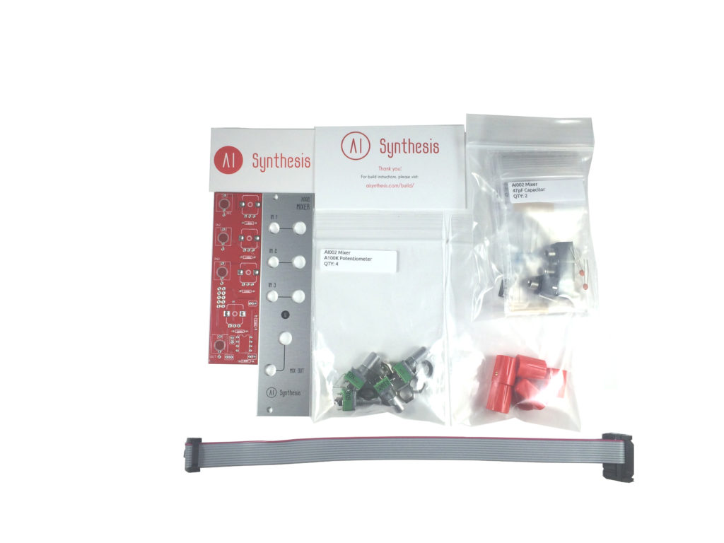
- As always, the first step is to gather your parts.
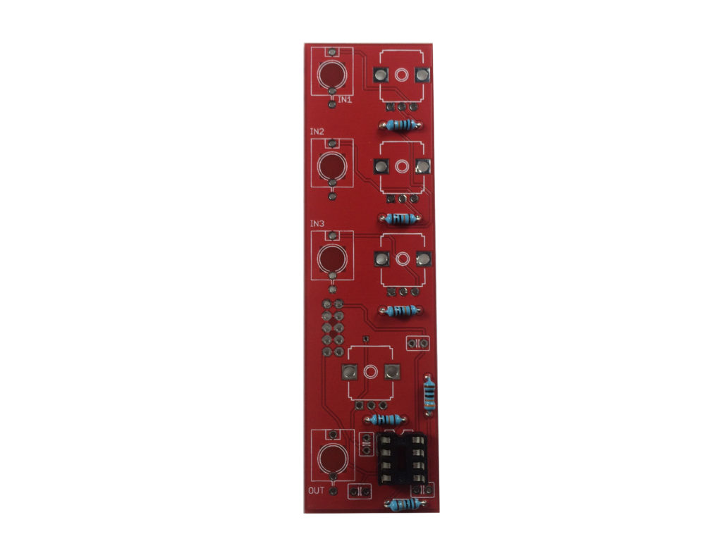
- In general with diy electronics, we want to build “low to high.” “Low to High” means soldering items in reverse order of height, as it is easier to manipulate smaller items when there aren’t taller things to get in the way. In this case, it means starting with the resistors. Start by soldering the 330R resistor, and the five 100k resistors.
Resistors are pretty near indestructible, so take your time. Heat the connection for about half a second before you apply solder. This pre-heating will prevent the molten solder from hitting cold metal and cooling too fast. This results in what’s called a ‘cold solder joint’, which is a loose connection where the solder did not adhere to the metal. These can be very frustrating, as at a casual glance will they will often appear to be good connections, and only upon close examination will one see the cracks, The technique (which becomes automatic after a while) is to put the tip on the connection first, and then apply the solder. Once the solder is on the joint, you hold the iron there for another half second, and pull the iron away. If the solder doesn’t flow easily, perhaps you haven’t allowed your iron to warm up, or you need to clean your iron tip. I like a temperature of about 550 degrees Fahrenheit (287 Celcius) for leaded solder.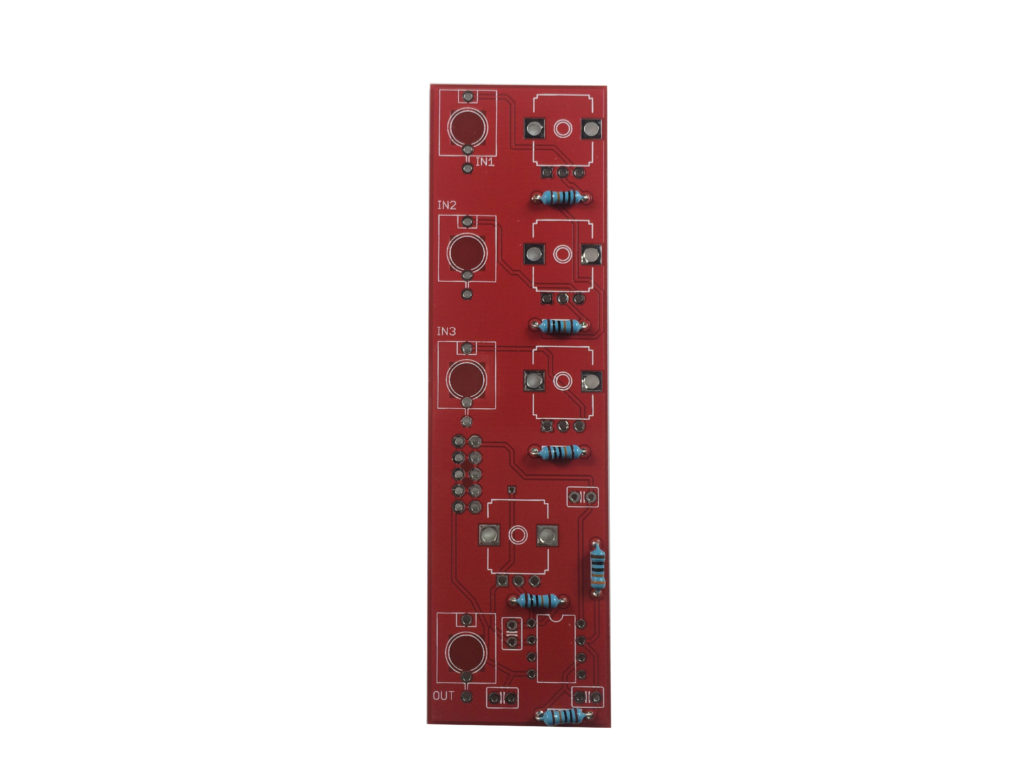
- Let’s move on to the IC Socket (not the IC!). We use sockets because some ICs are susceptible to damage from heat. The socket serves as a simple “plug” for the IC. Be sure to align the notch in the socket with the one on the silkscreen. We solder the socket in, and then later we’ll just insert the IC. This not only protects the IC from heat from soldering, it also makes the IC very easy to replace should it go bad. Insert the IC, and bend the tips on the rear of the pcb to hold it in my place while you solder.
- With the resistors and socket in place, we’ll solder in the capacitors. Start with the .1uf caps. There was an issue with the PCB printing, and the cap values were not printed. This will be corrected in future builds, and we deeply regret the error.
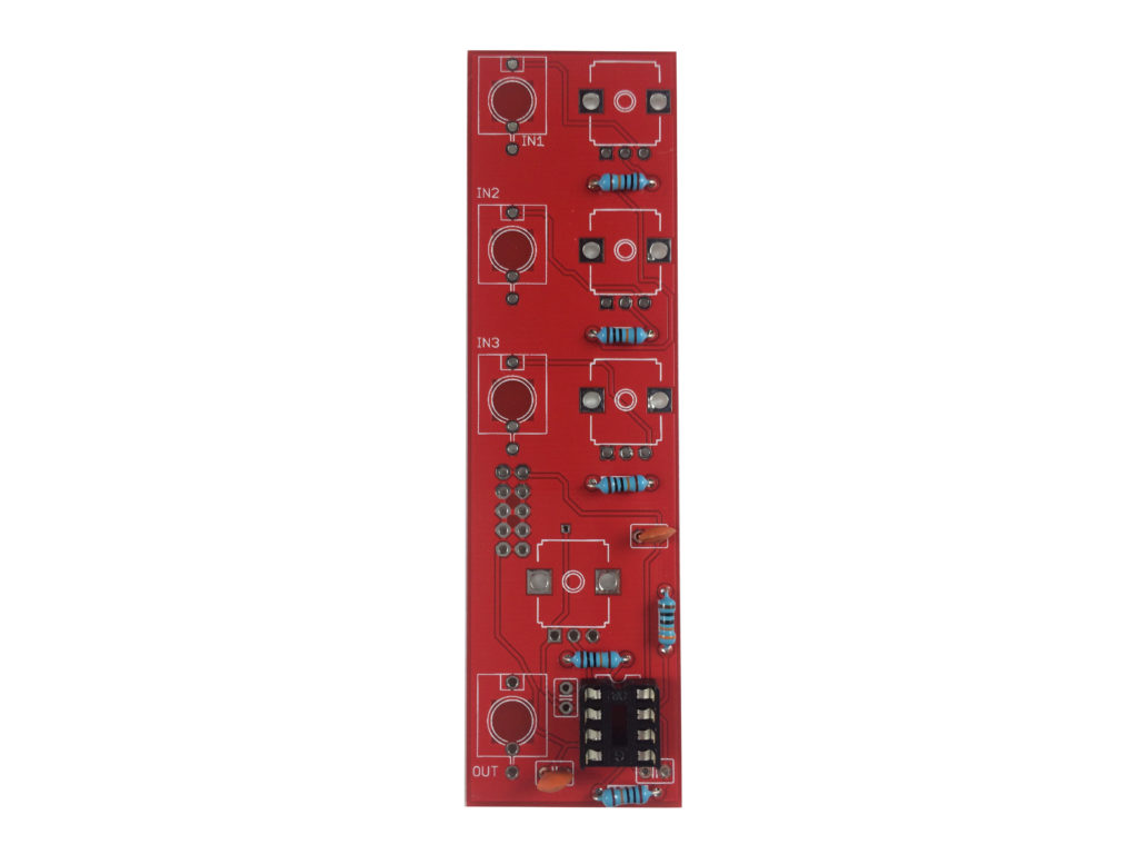
- Then solder in the 47pF caps.
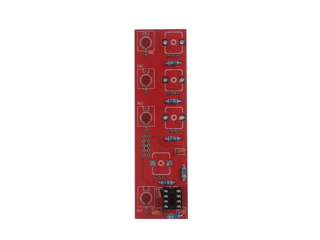
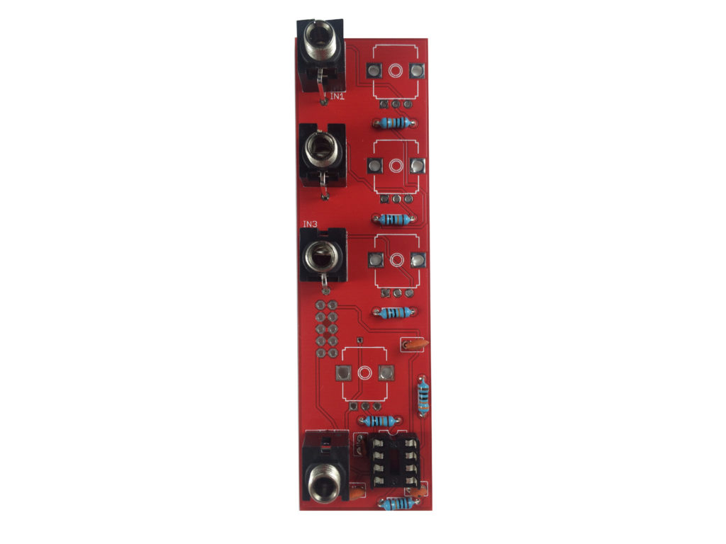
- Solder in the 4 jacks. They only fit in one way.
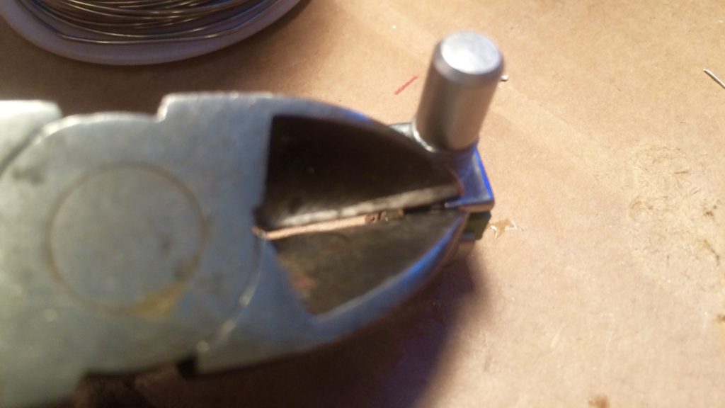
- Time for the potentiometers, which will read A100K, or A104. These are your knobs, and will also mount the PCB to the panel along with the jacks. Before you solder them, inspect your potentiometer to see if your pots have "nibs" that rise above the base of the pot. If so, use your cutters to snip off the tab that comes on the pot:
 You want the potentiometers to rest as close to 90 degrees from the PCB as you can, but the pins are a bit flexible, so they can be fudged. Don’t fudge too much though, or the pins will break, and you’ll need a new pot! These pots are all A100k, so it doesn’t matter which pot goes where, they are all the same.
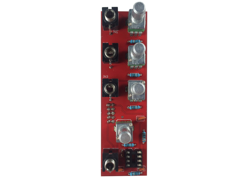
- Finally insert the IC. Make sure it is in there snugly, and flush against the socket, with the black dot near, and to the left of the socket notch.
- Solder in the two rows of 5 pins into the solder holes. This is where you will apply power to the module - don’t do it yet though! You may want to insert the two header rows into the power cable to help you solder these in straight. Newer kits have the shrouded header. When I designed this circuit, my parts supplier didn't have shrouded headers, but they do now and newer kits have those. They won't sit 100% well without cutting some pins from jacks and pots, so I had to make a hard decision between a cleaner 2x5 connector that was not keyed, or a shrouded power connector that was keyed to avoid plugging in the cable backwards, but not sit perfectly well. I went with keyed headers in the end. The next PCB design will be better spaced for the keyed header.
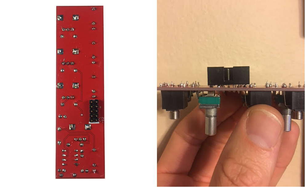
1st Gen (old PCBs)
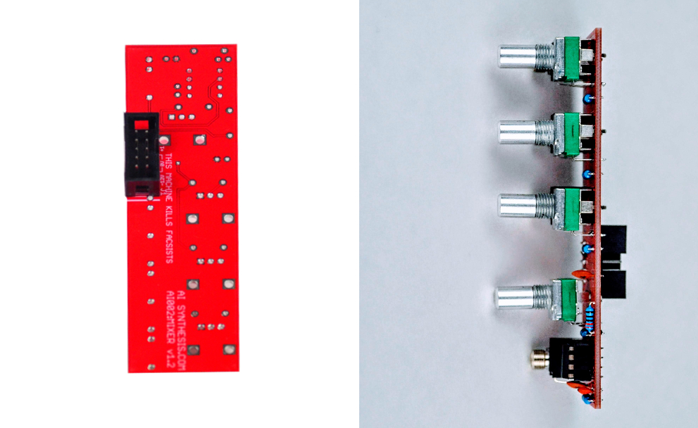
Current PCBs
- Before you put on the panel, let's test the module. Without applying power, ensure that there is no continuity between the positive, ground, and negative voltage power pins using a digital multi-meter. Put your multimeter in continuity test mode and test the module before applying power.
You test by connecting one test lead of the multimeter to ground and the other to positive voltage. There should be no continuity.
Next test by connecting one test lead of the multimeter to ground and the other to negative voltage. There should be no continuity.
Next test by connecting one test lead of the multimeter to positive and the other to negative voltage. There should be no continuity. Assuming there is no continuity there, you are good to apply power. Eurorack, tragically, has no universal power connector format. This has resulted in far too many blown up modules. AI synthesis modules follow the most common format, in which there is a white stripe next to the negative end of the power connector, and this is typically where the red stripe of the power cable should be aligned, but check your power supply for details.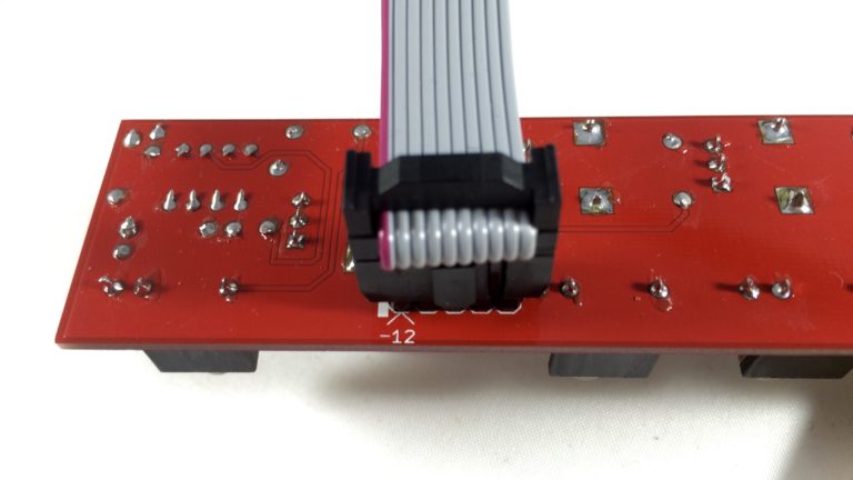 I like to give a freshly powered module a few seconds to ensure that nothing smokes and there is no danger of fire. This is why it is nice to have a bench power supply to test a module apart from your Eurorack system. If everything looks good, you are good to test prior to applying the panel and finishing up.
 - The three pots on the right are all passive attenuators, they don't boost signal, they just lower them. Fully clockwise, they let all of the input signal in, as you move it counter-clock wise, attenuation is applied to the signal, and it is lowered. The lower, center pot regulates feedback resistance of the IC. At center, the signal is roughly at unity (the same volume as coming in - minus the 100k input protection resistors). Past unity, turning this knob up will eventually cause distortion and erratic signal. This can be fun. Insert a signal from an oscillator or mp3 player into an input with the lower, centered mix pot at 12' o clock. With the input volume knob fully clock-wise you should hear the signal in the output (via headphones or other speaker). Repeat this test with each of the inputs. If everything works, you are good to put on the panel and finish up.
- Peel the protective film from the aluminum panel, and place it over the jacks and pots. Apply the knob washers and nuts to the pots, and the jack nuts to the jacks. Now carefully tighten the nuts. You can use a nut driver, or your wire strippers if you are careful.
- Place the red knobs on the pots. You will probably want to loosen the set screws to put them on, and then adjust them. I like to put them on with the knobs turned fully counter-clockwise, but you can do it however you like. Potentiometers are only precise to =/1 20%, so it's not overly critical. Once they are on, where you want them - tighten the set screws. Test again, and enjoy your new mixer!
- Share your build on Facebook and Instagram!
- If you are having any issues at all, please contact me at: https://aisynthesis.com/contact/.