
How to Build the AI012 Wave Animator
This is the build guide for the AI012 DIY Wave Animator
Table of Contents
- Resources
- About the AI012 Wave Animator
- Tools Needed
- BOM (Bill of Materials)
- Build Guide
1. Resources
2. About the DIY AI012 Wave Animator
The AI012 Eurorack Wave Animator produces two pulses per input wave cycle with voltage controlled pulse width, distance, and amplitude of the second pulse.
3. Tools Needed
- Soldering Iron: Cheap
or Nice
- Solder
- Soldering Tip Cleaner
- Micro-Shear Flush Cutter
For testing and Calibration:
4. BOM
| Category | Part | Quantity | Designation |
|---|---|---|---|
| Capacitor | 10uF Capacitor | 2 | C1-2 |
| Capacitor | .1uF Capacitor | 4 | C 3-6 |
| Diode | 1N4148 | 2 | D3-4 |
| Hardware | Shrouded Power Header | 1 | Power |
| Hardware | UnShrouded Header | 1 | Expander In |
| Hardware | Jack | 5 | In, PWIN, PPIN, P2AMOD, Out |
| Hardware | Nut | 5 | |
| Hardware | 14 Pin IC Socket | 3 | IC1, 3, 4 |
| Hardware | 16 Pin IC Socket | 1 | IC6 |
| Hardware | 6 Pin Plug | 2 | J1, 3 |
| Hardware | 6 Pin Socket | 2 | J2, 4 |
| IC | TL074 | 3 | IC1, 3, 4 |
| IC | LM13700 | 1 | IC6 |
| Potentiometer | 9mm Alpha Potentiometer B100K | 3 | P2AMP, P2MOD, PP, PP-IN, PW, PW-MOD |
| Potentiometer | Tall Trimmer Potentiometer B100K | 3 | PWIN, PPIN, P2AMOD |
| Regulator | 78L05 | 1 | IC7 |
| Resistor | 10 Ohm Resistor | 2 | R1-2 |
| Resistor | 100K Resistor | 17 | R11, R12, R15, R18, R19, R20, R21, R24, R25, R26, R28, R30, R32, R35, R38, R44, R45 |
| Resistor | 10K Resistor | 1 | R41 |
| Resistor | 27K Resistor | 1 | R42 |
| Resistor | 120K Resistor | 2 | R29, 31 |
| Resistor | 150K Resistor | 2 | R33, 34 |
| Resistor | 1K Resistor | 2 | R39, 40 |
| Resistor | 3.3K Ohm Resistor | 2 | R14, 27 |
| Resistor | 47K Ohm Resistor | 2 | R13, 43 |
| Resistor | 220K Resistor | 6 | R16, R17, R22, R23, R36, R37 | Transistor | 2n3906 | 1 | T2 |
5. Build Guide

- As usual, we solder from "low items to high items." First solder the two 10 ohm resistors. These act as fuses in case power is reversed.
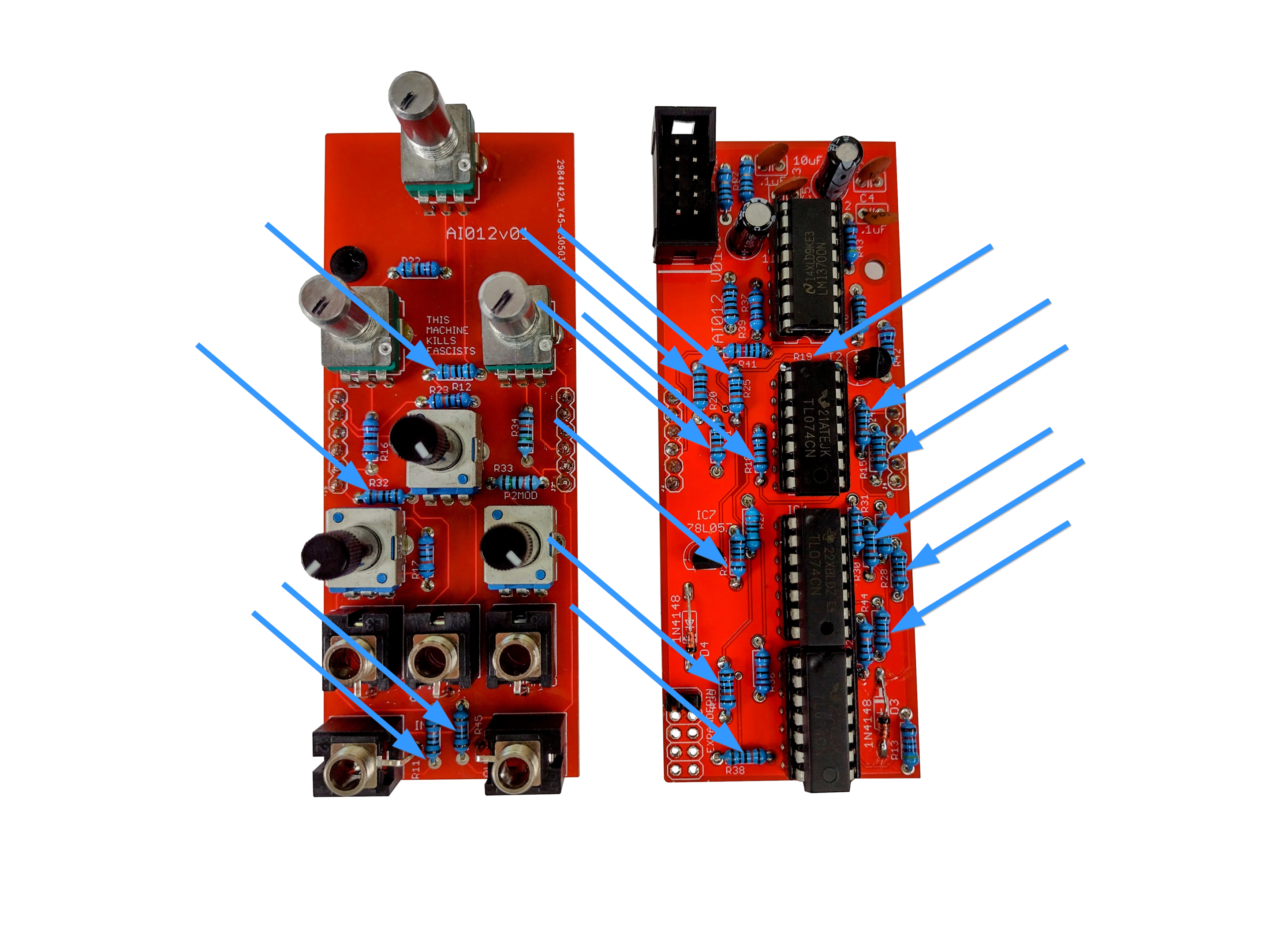
- Now solder the seventeen 100K resistors.
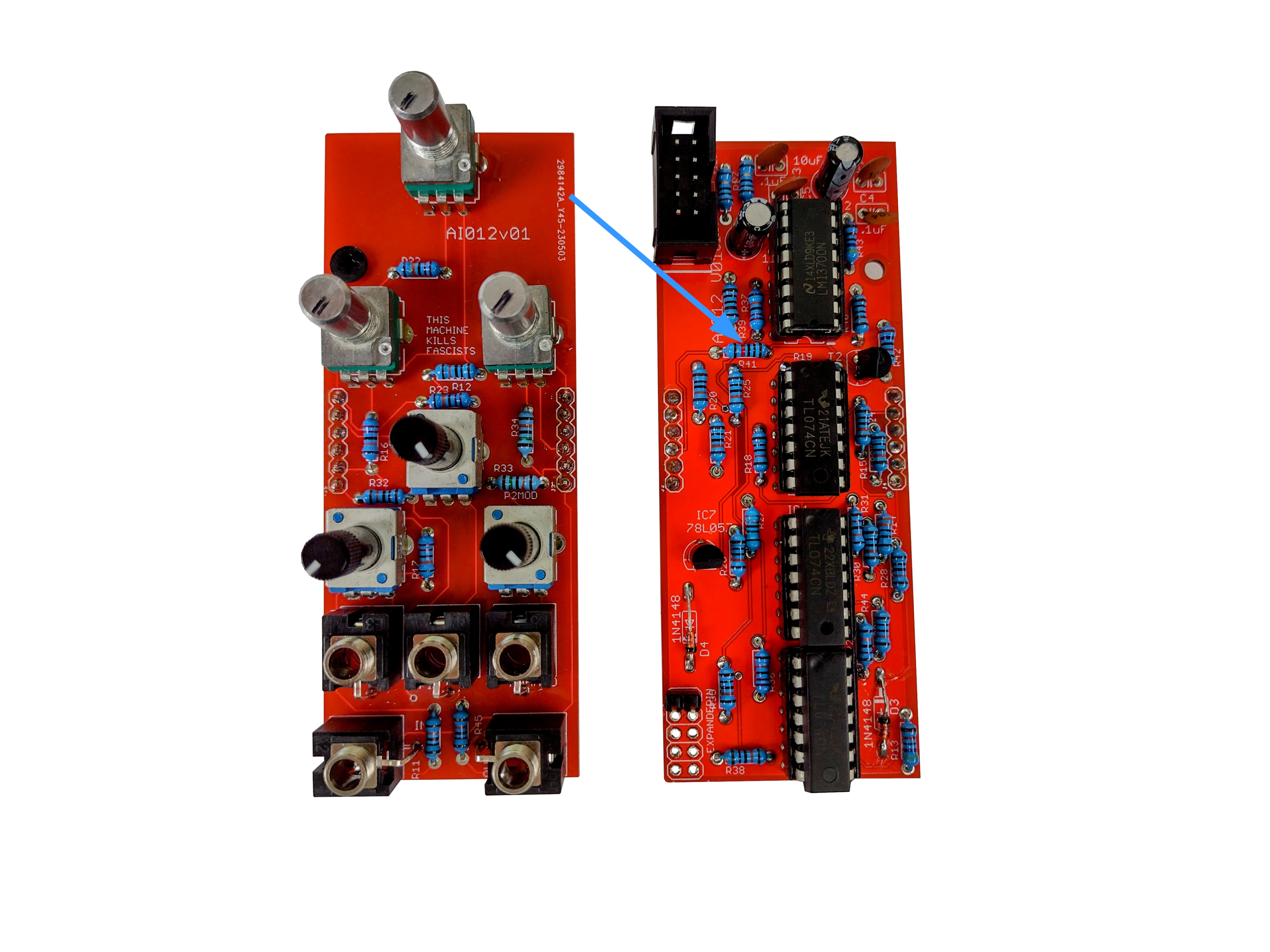
- Now solder the single 10K resistor.
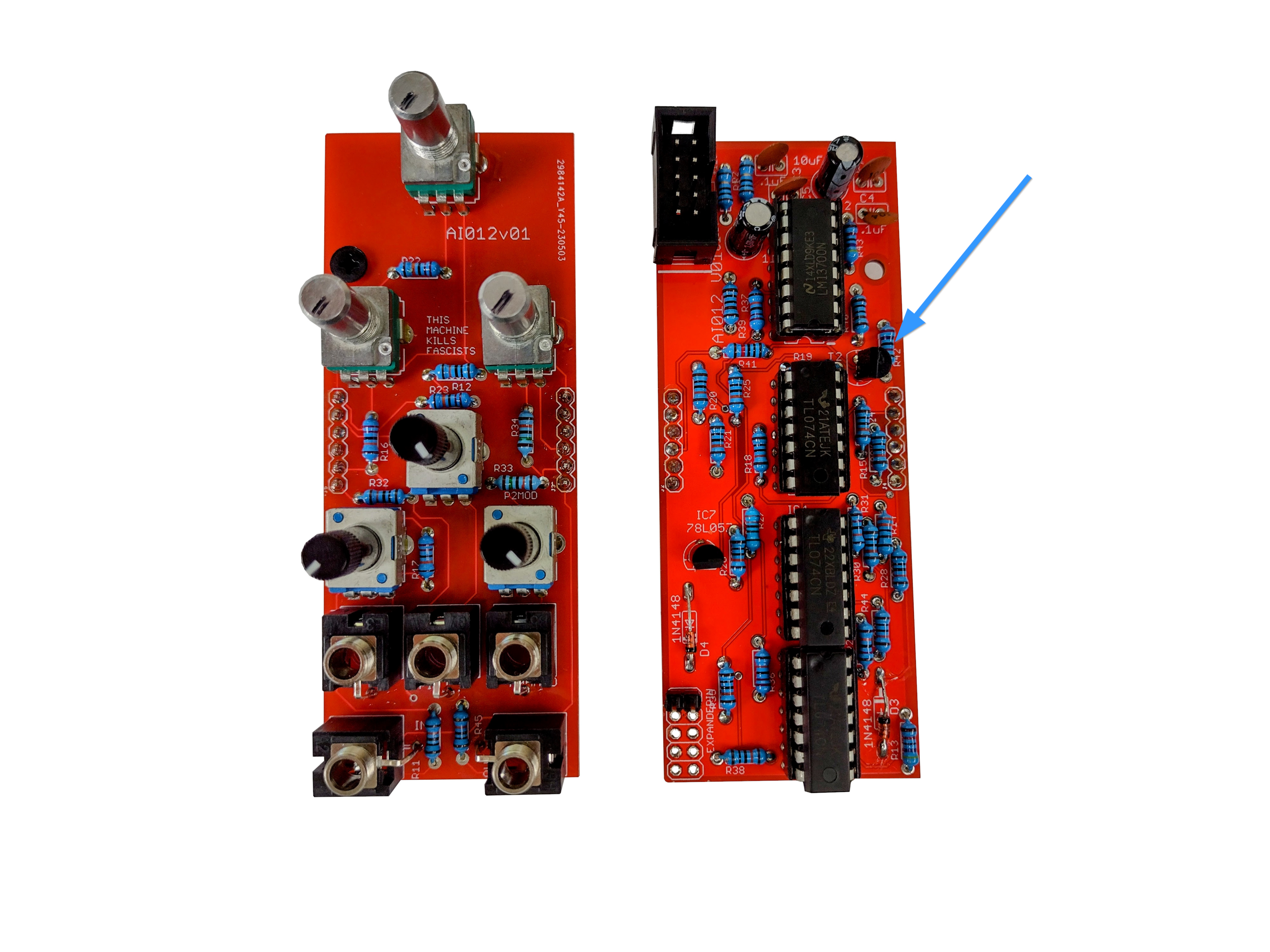
- There is one 27K Resistor at R42 (this design went through A LOT of revisions, so the designations are kind of nuts).
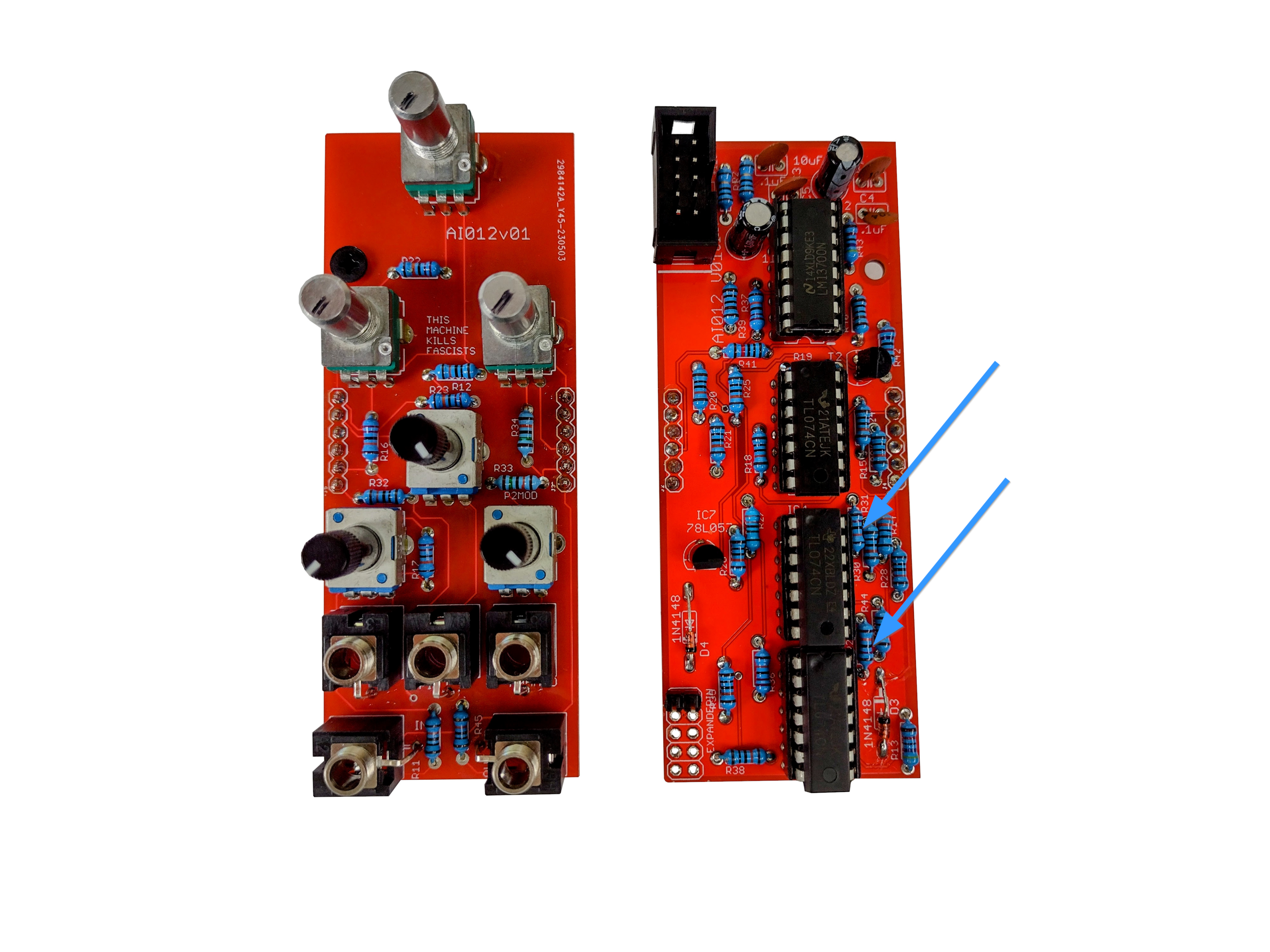
- There are two 120K resistors.
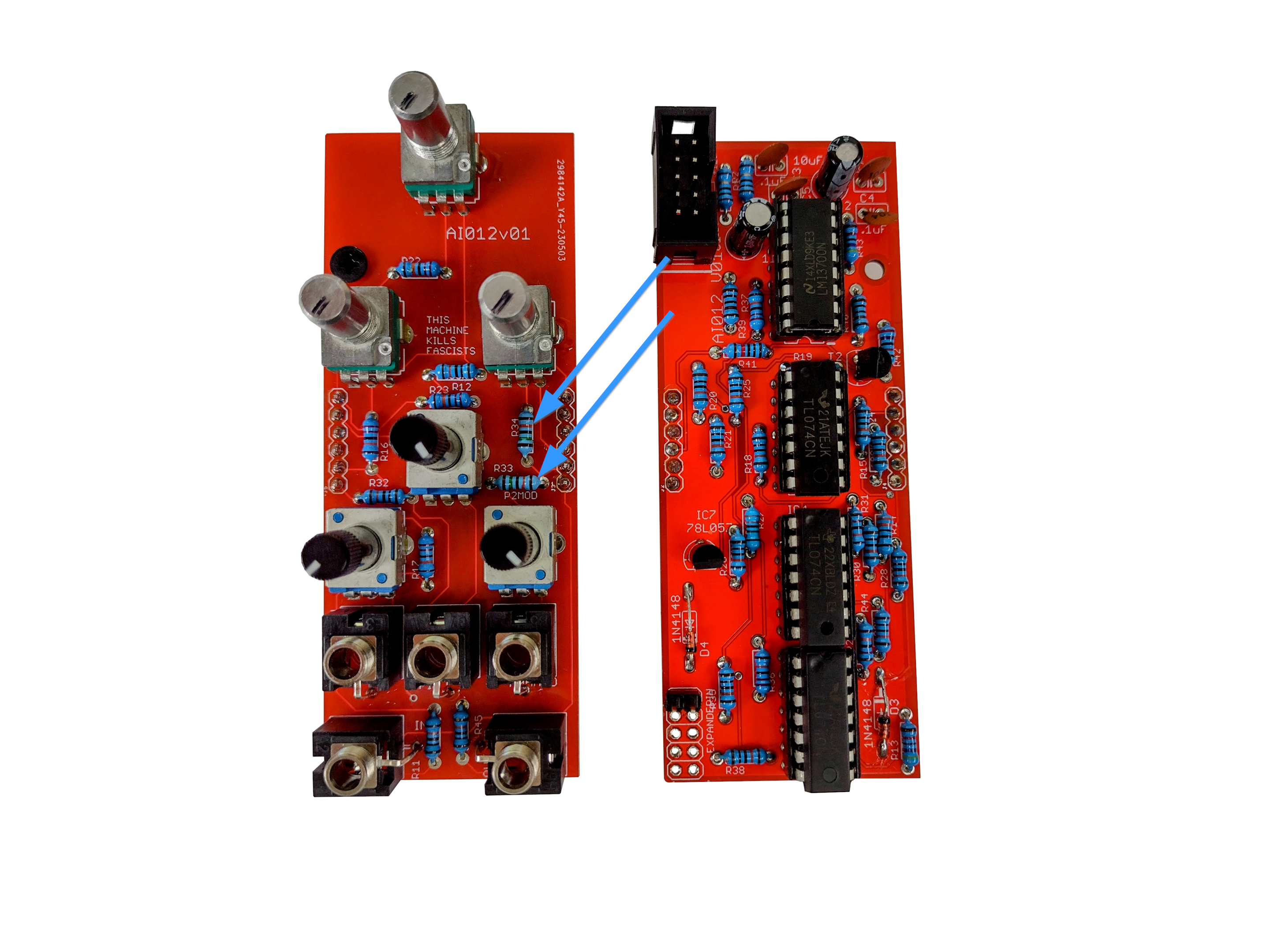
- Now solder the two 150K resistors.

- There are two 1K resistors.
- There are two 3.3K resistors.
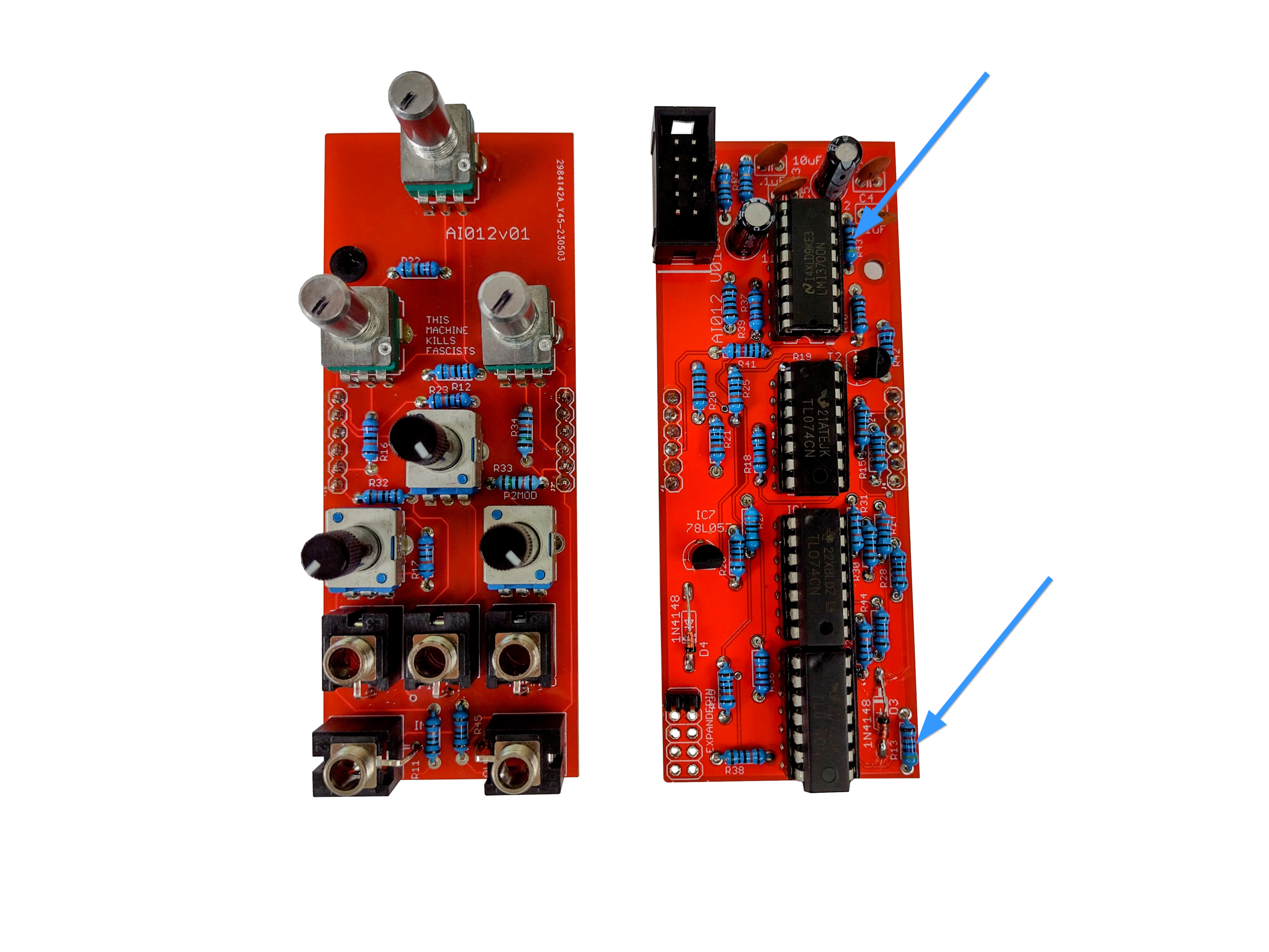
- Now solder the two 47K resistors.

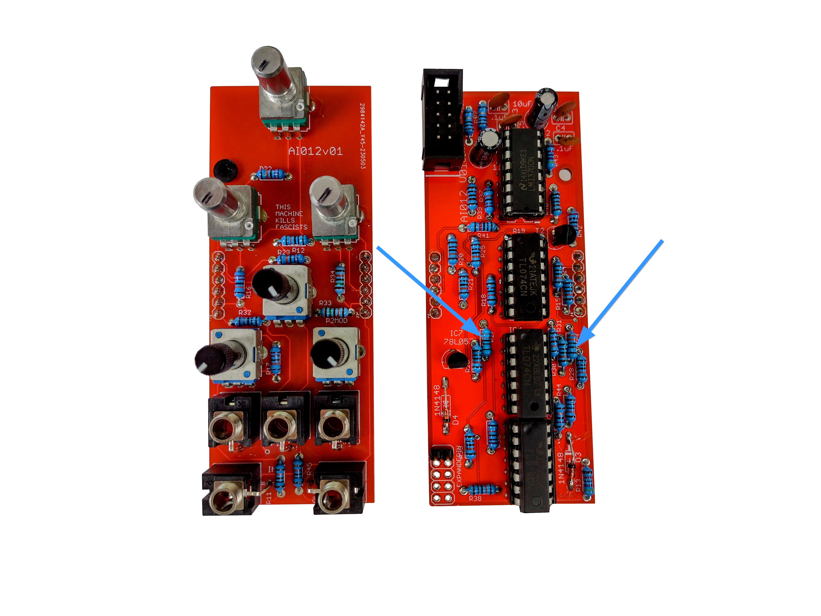
- Now solder the six 220K resistors.

- There are two 1N4148 Diodes.

- There is a 78L05 voltage regulator at IC7.

- There a 2n3906 transistor at T2. Judgment day upon all those who omit this transistor.
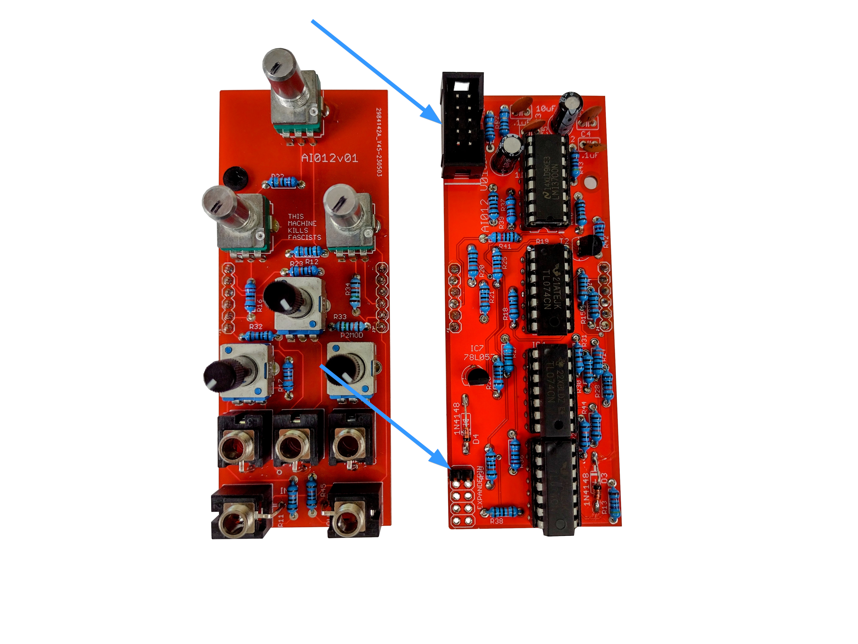
- There are 2 headers. Mind the orientation of the shrouded power header (top), and solder the un-shrouded header at the expander port.
- Now we'll start on the caps. There are four .1uF caps.
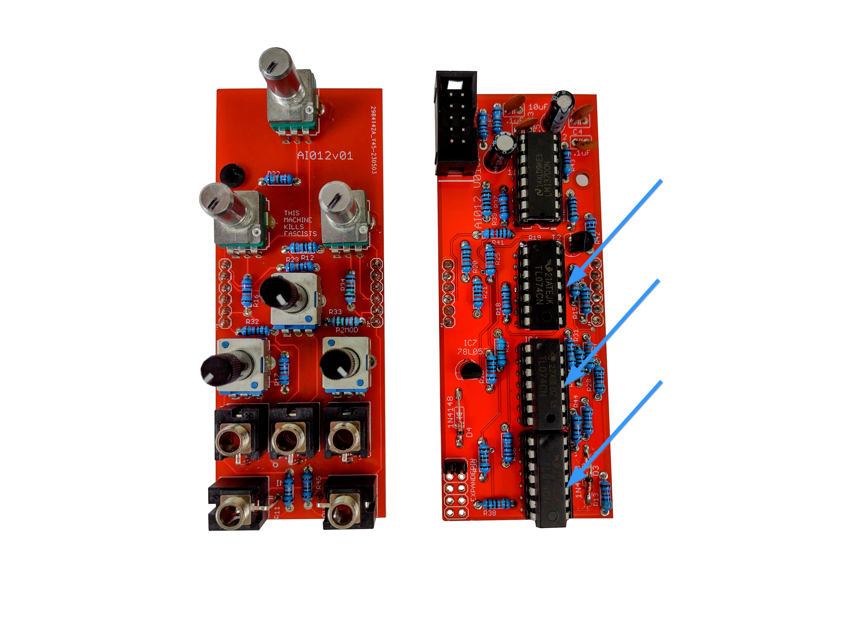
- There are three 14 pin headers. Even though IC sockets have no polarized parts themselves, orient the divot pointing up (towards the shrouded power header) to help you correctly insert the TL074 ICs (pointing up).

- The 16 pin IC socket should be placed pointing down - opposite the 14 in header - as that IC will point down.
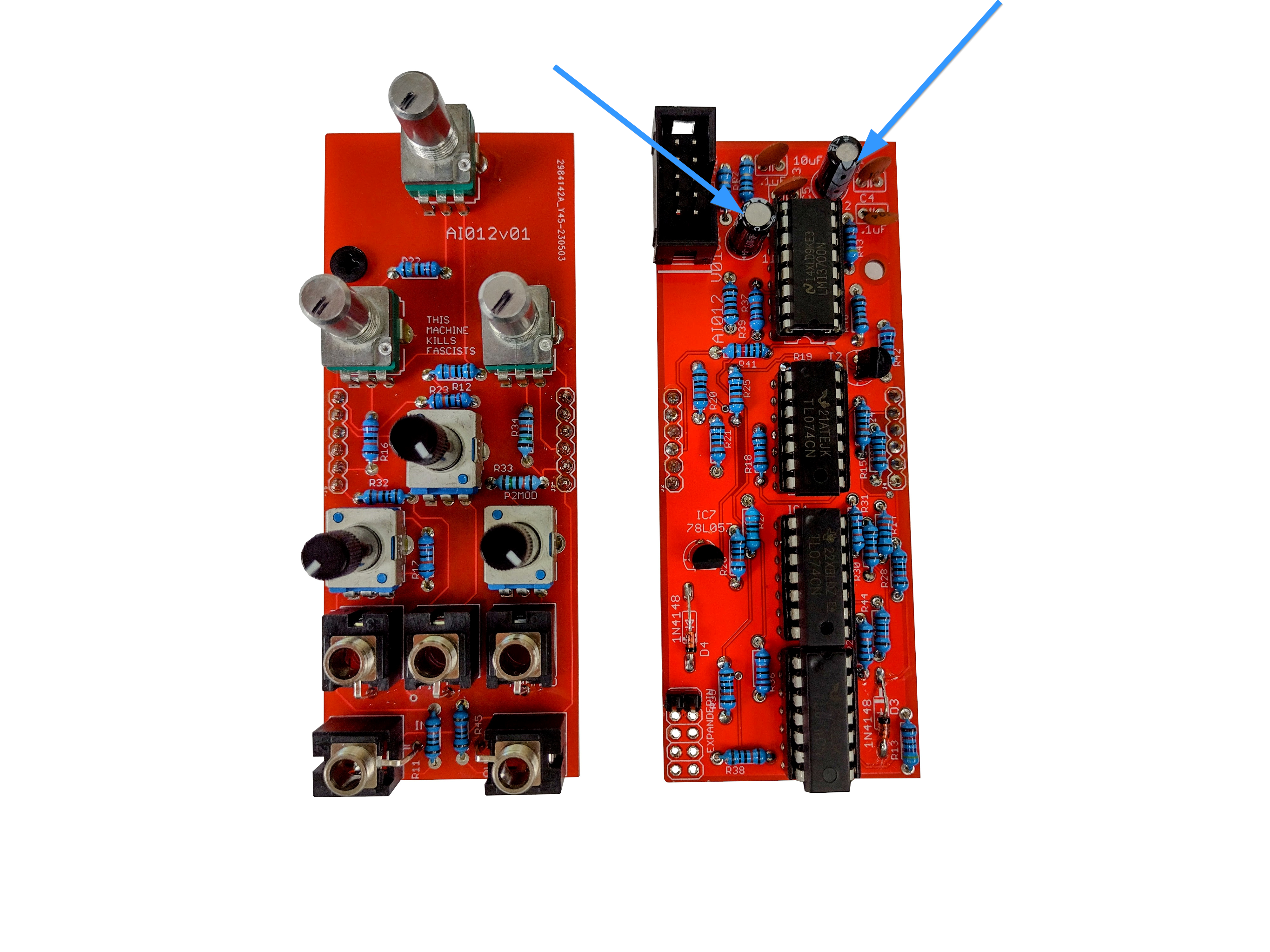
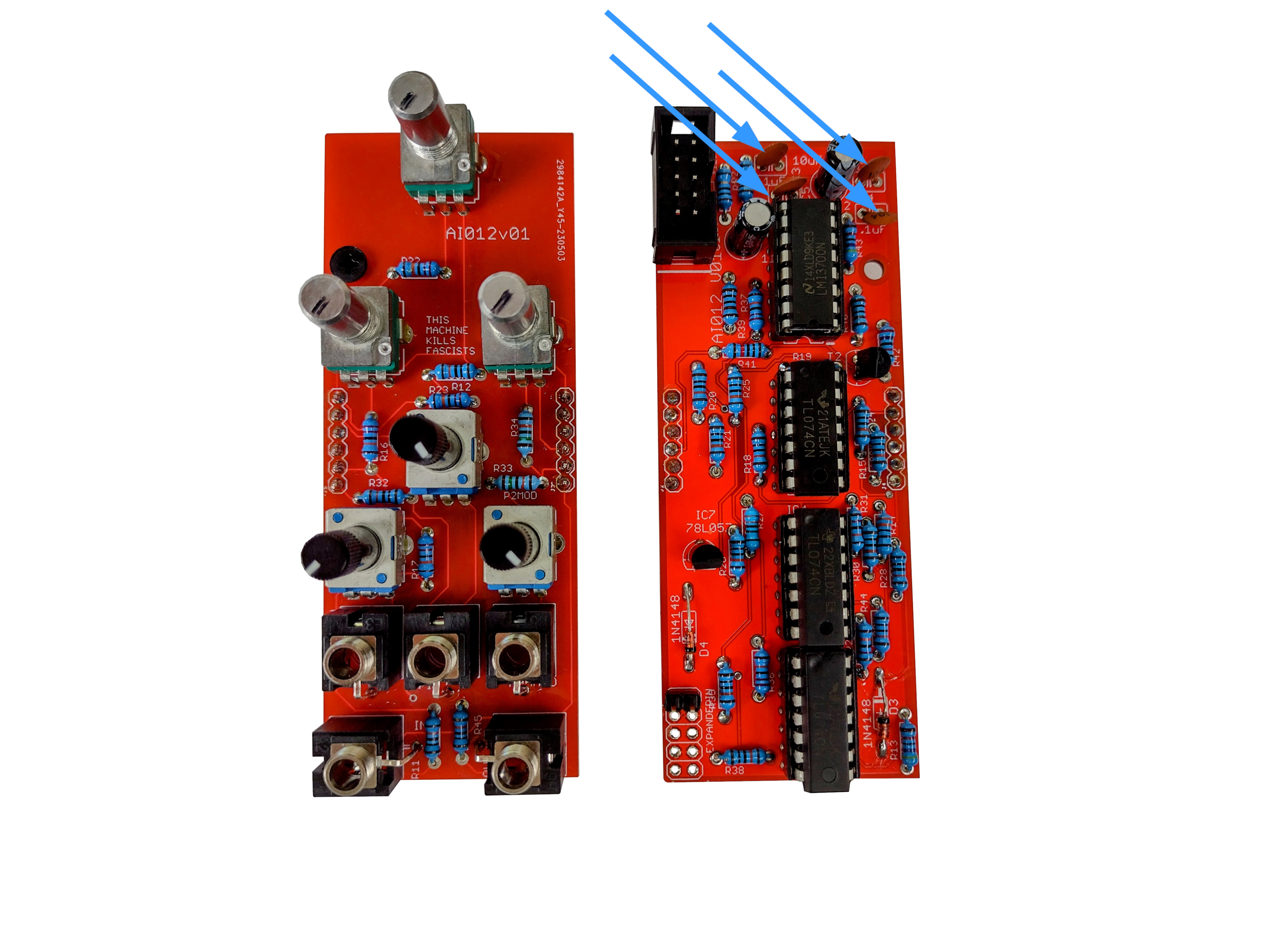
- There are two 10uF polarized caps - mind the orientation of these. The white stripe indicates the negative side.
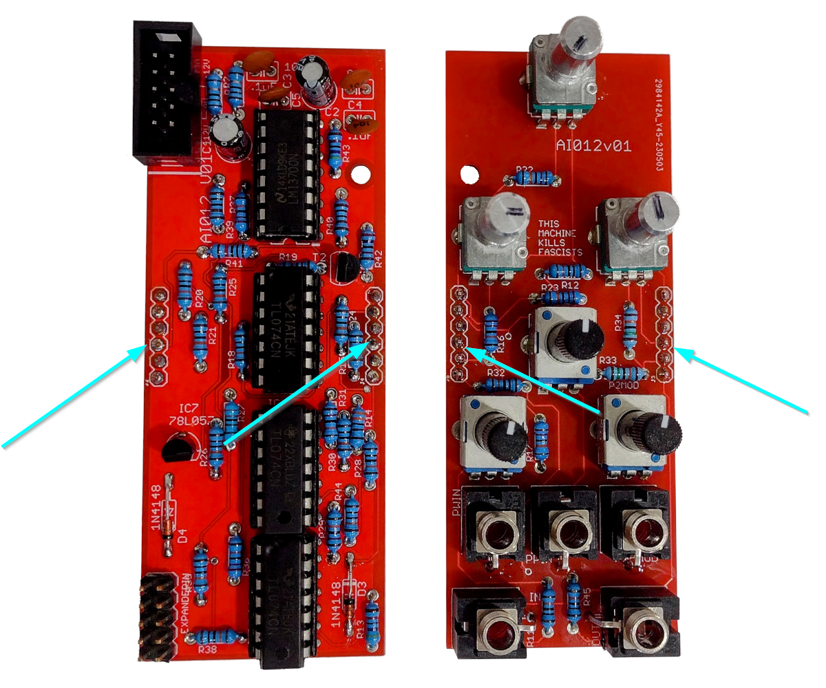
- Now insert the 6 pin sockets and plugs. These will connect the two PCBs and carry signals between the two. I put the control side down, insert the plug and sockets connected, and then put the side with the ICs (facing you) on to that and start soldering.
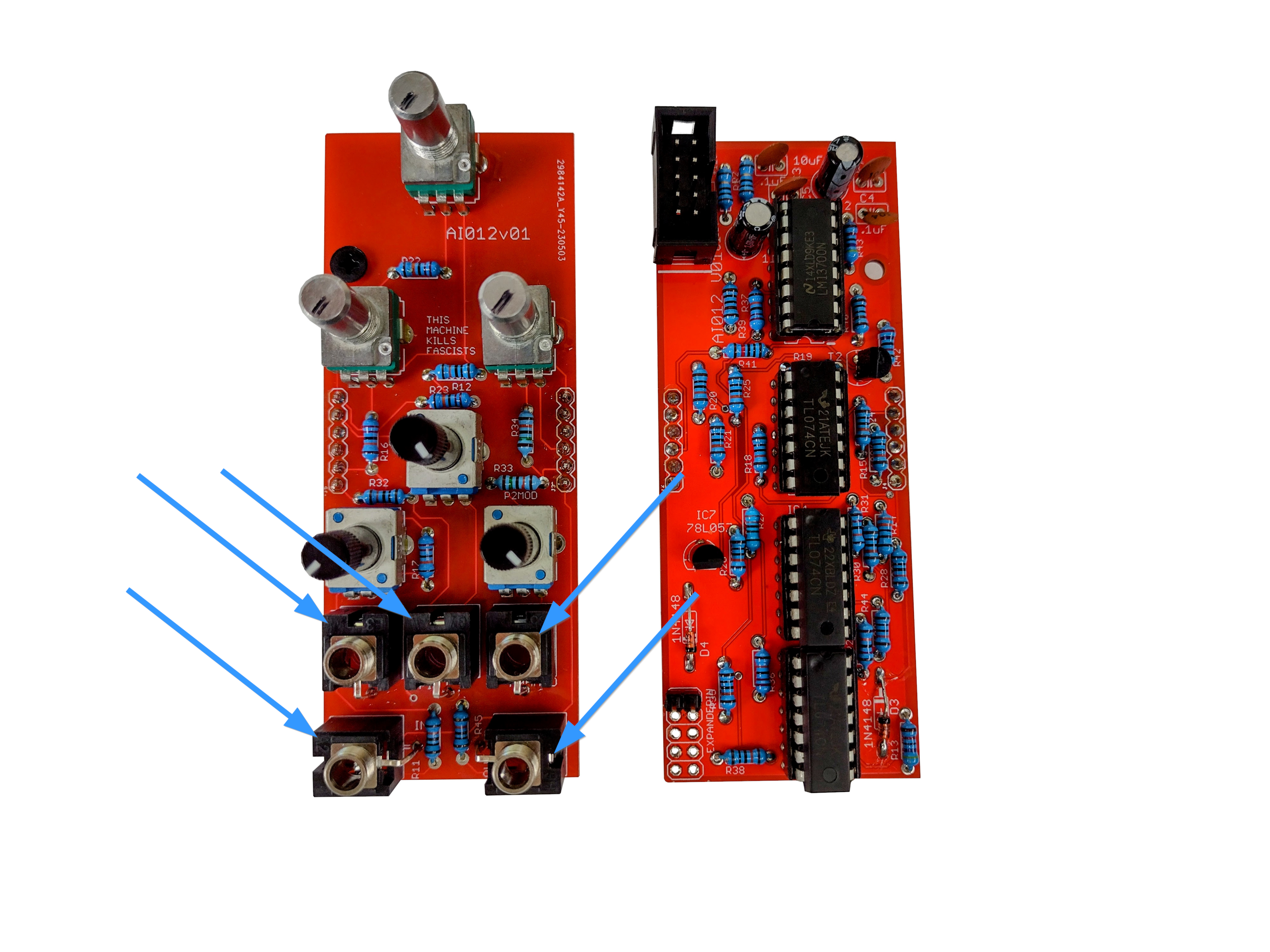
- Now that we are done with those we can solder in the jacks. I like to start with the ground lugs on the top side of the PCB to ensure they are flat, and then turn it over to finish them.

- Now solder the pots I usually put on the pots and tall trimmers, then place the panel on and tighten a few jack nuts to keep it on. Then I ensure the pots all turn correctly and aren't slanted, and then I turn it over and solder them in.

- Now solder in the three A100k tall trimmers if you didn't do that in step 21.
- Now perform a Continuity Test, insert ICs if you haven't allready and power on.
Congratulations!
Share your build on Facebook and Instagram!
If you are having any issues at all, please contact me at: https://aisynthesis.com/contact/.