
How to Build the AI017 DIY Eurorack Low Pass Gate
This is the build guide for the AI017 DIY Low Pass Gate Module
Table of Contents
- Resources
- About the AI017 Eurorack DIY Low Pass Gate
- Tools Needed
- BOM (Bill of Materials)
- Build Guide
1. Resources
2. About the DIY Eurorack Low pass Gate
This DIY Eurorack Low Pass Gate uses uses vactrols to create a classic VCA/VCF/Combination module essential for West Coast Synthesis. The Low Pass Gate is a low pass filter with range near sub-sonic, thus even in "VCA" mode, the output loses high frequency as control voltage falls, mimicking the way "natural" sounds decay. Unlike traditional low pass gates that cannot fully close, this module features an optional Depth control to fully close the module. There is also a trimmer on the rear to control the gain in the filter resonance circuit - allowing for mellow resonance or wild distortion.
3. Tools Needed
- Soldering Iron: Cheap
or Nice
- Solder
- Soldering Tip Cleaner
- Micro-Shear Flush Cutter
For testing and Calibration:
4. BOM
| Category | Part | Quantity | Designation |
|---|---|---|---|
| Capacitor | 10uF Capacitor | 2 | C1-2 |
| Capacitor | .1uF Capacitor | 4 | C3-6 |
| Capacitor | 1uF Polyester Capacitor | 1 | C7 |
| Capacitor | 220pF Capacitor | 1 | C8 |
| Capacitor | 4.7nF Capacitor | 1 | C9 |
| Capacitor | 22pF Capacitor | 1 | C10 |
| Capacitor | 1nF Capacitor | 1 | C11 |
| Capacitor | 2.2nF Capacitor | 1 | C12 |
| Diode | 1N4730 Diode | 1 | D1 |
| Hardware | Shrouded Power Header | 1 | Power |
| Hardware | 14 Pin Socket | 1 | IC1 |
| Hardware | 8 pin Socket Header | 2 | J1, 2 |
| Hardware | 8 pin Plug Header | 2 | J3, 4 |
| Hardware | Jack | 4 | In, Out, CV1, CV2 |
| Nut | Nut | 4 | |
| IC | TL074 | 1 | IC1 |
| Potentiometer | 9mm Alpha Potentiometer A100K | 1 | Q |
| Potentiometer | 9mm Alpha Potentiometer A500K | 1 | Depth |
| Potentiometer | 9mm Alpha Potentiometer B50K | 1 | Freq |
| Potentiometer | 9mm Tall Trimmer A100K | 1 | In |
| Potentiometer | 9mm Tall Trimmer B100K | 1 | CV2 |
| Resistor | 10R OR 1n5817 Diode | 2 | R1-2 |
| Resistor | 100K Resistor | 6 | R3-5, 12, 19, 21 |
| Resistor | 10K Resistor | 3 | R8, 10, 16 |
| Resistor | 150K Resistor | 1 | R20 |
| Resistor | 15K Resistor | 2 | R6-7 |
| Resistor | 1K Resistor | 1 | R11 |
| Resistor | 33K Resistor | 1 | R13 |
| Resistor | 4.7M Resistor | 1 | R9 |
| Resistor | 470K Resistor | 1 | R18 |
| Resistor | 470R Resistor | 1 | R15 |
| Resistor | 51K Resistor | 1 | R17 |
| Switch | SPDT Switch | 1 | SW3 |
| Switch | 3pdt On-Off-On Switch. | 1 | S1 |
| Trimmer | 20K Trimmer | 1 | R14 |
| Vactrol | VTL5c3 | 2 | LDR1, 2 |
5. Build Guide
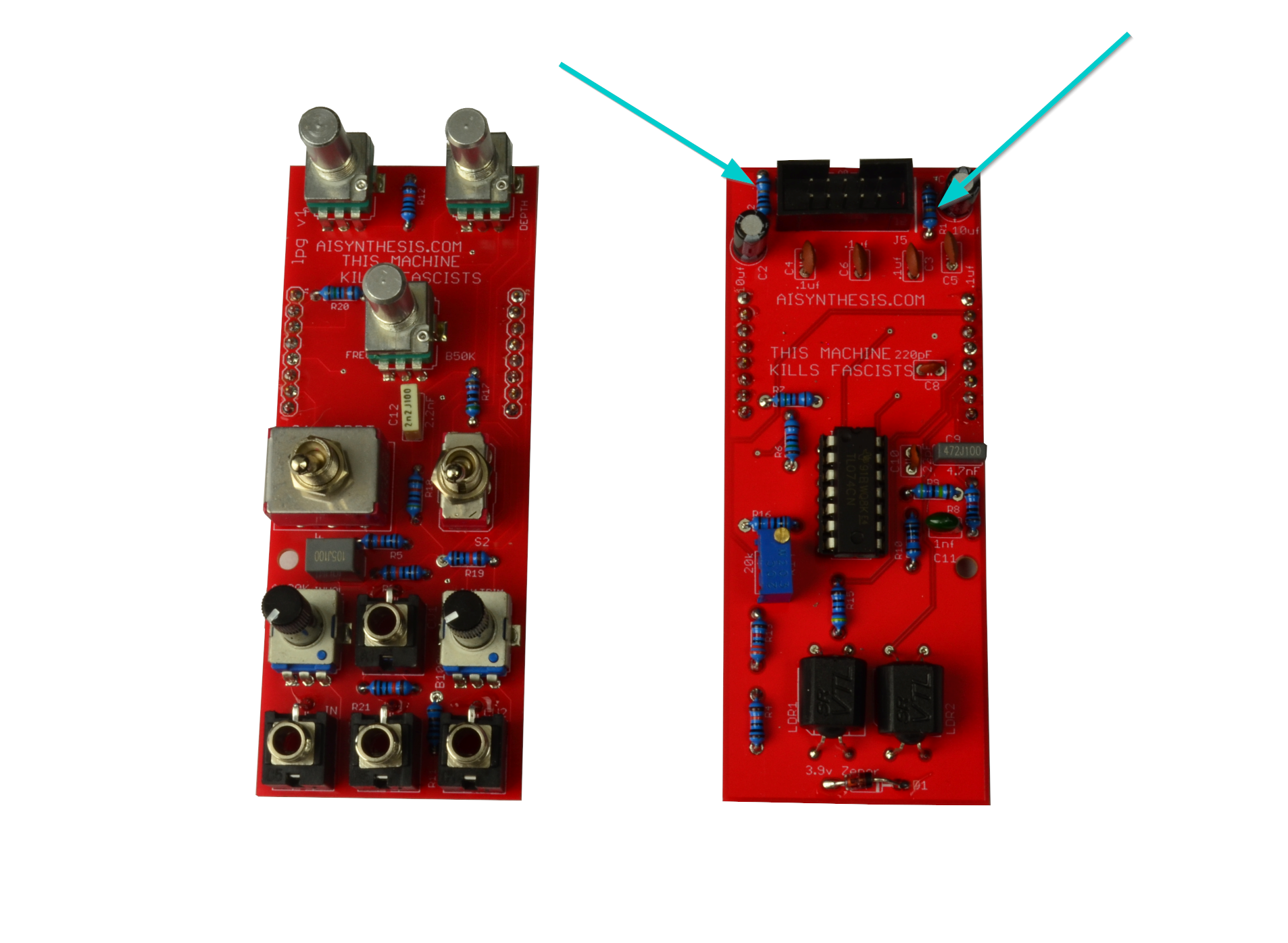
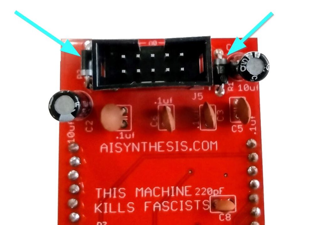
- First, gather your parts together, and start with the two 10R resistors OR 1N5817 Diodes at R1 and R2. Your kit may have either part, and both are fine. The kits are transitioning to using 1N5817 Diodes instead of 10 Ohm resistors for further reverse power protection. The 10 Ohm resistors are not polarized and have no orientation. The 1n5817 Diodes must be put in the correct orientation, shown below. When I re-order PCBs they will have the orientation on the PCB. I didn't want to throw out a bunch of otherwise good PCBs.
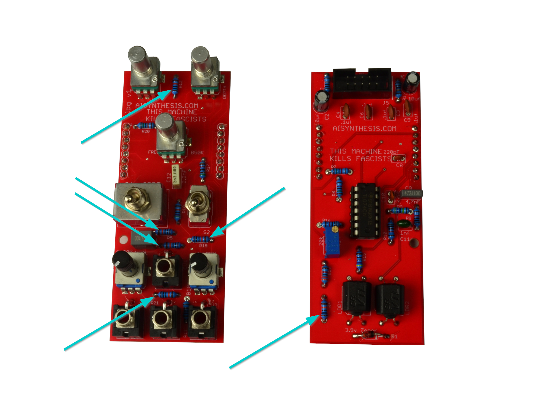
- Now solder the six 100k resistors.
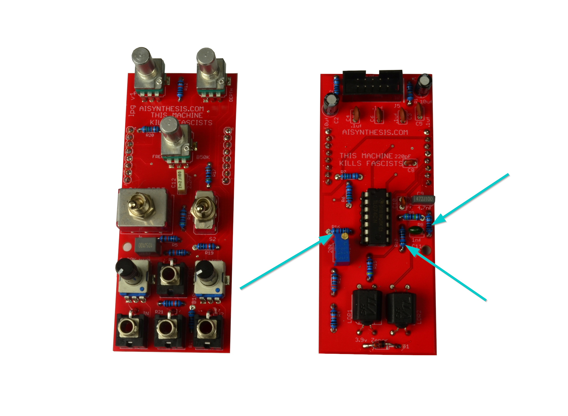
- Now solder the three 10K resistors.
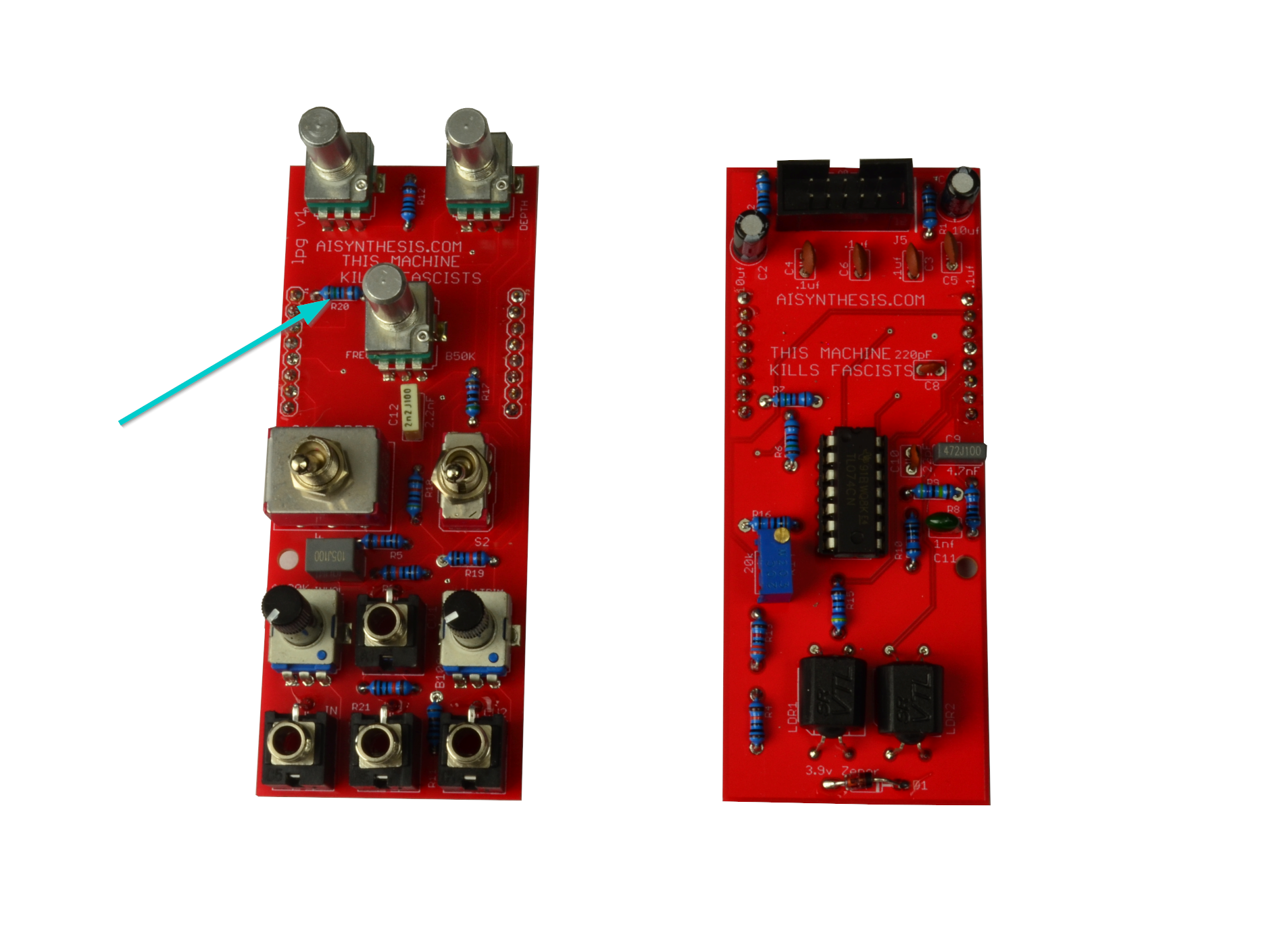
- There is one 150K Resistor at R20.
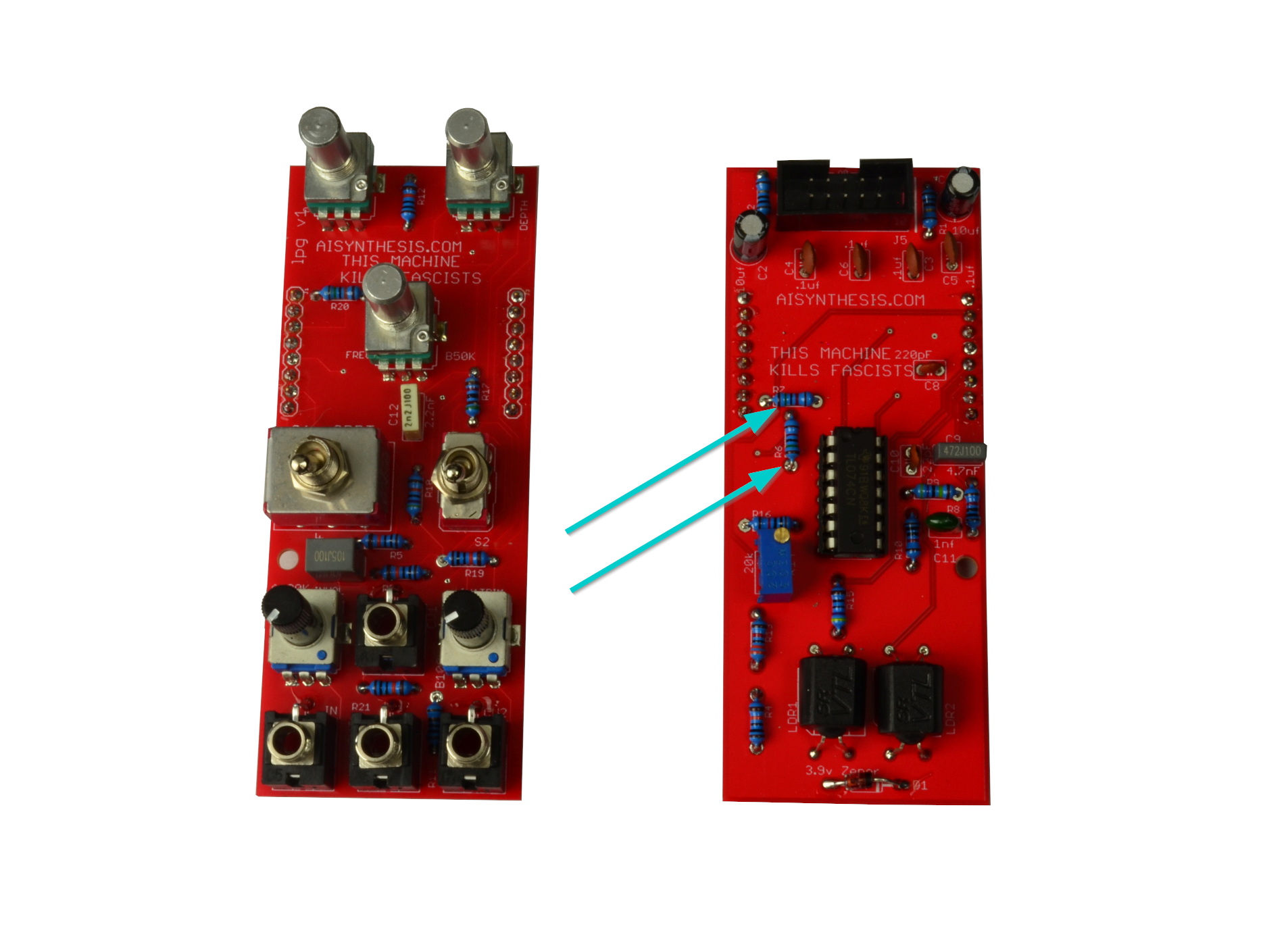
- There are two 15K Resistors at R6 and R7.

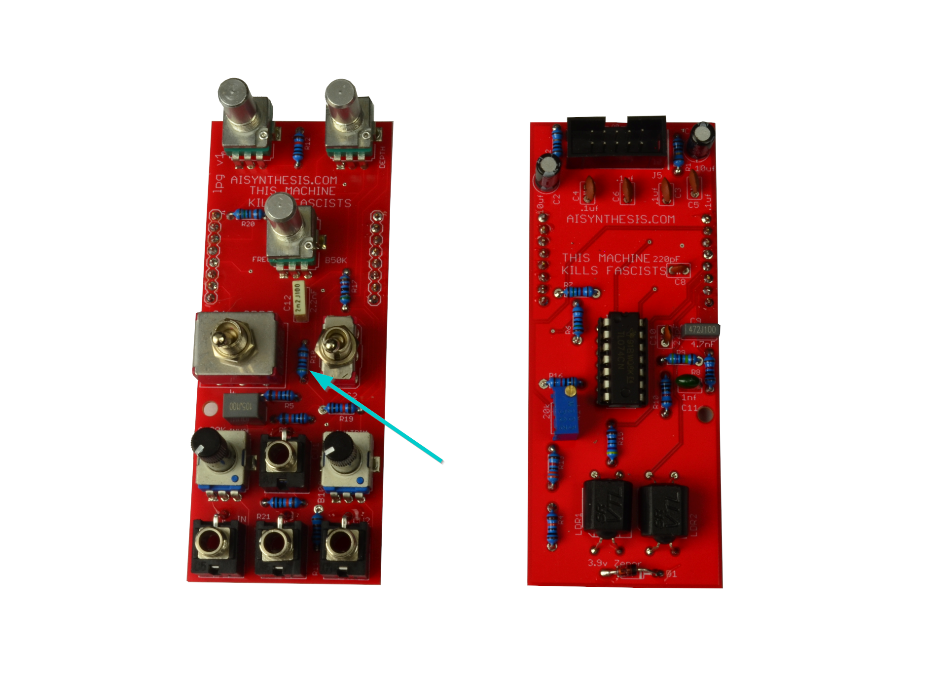
- Now solder the 1K Resistor at R11.
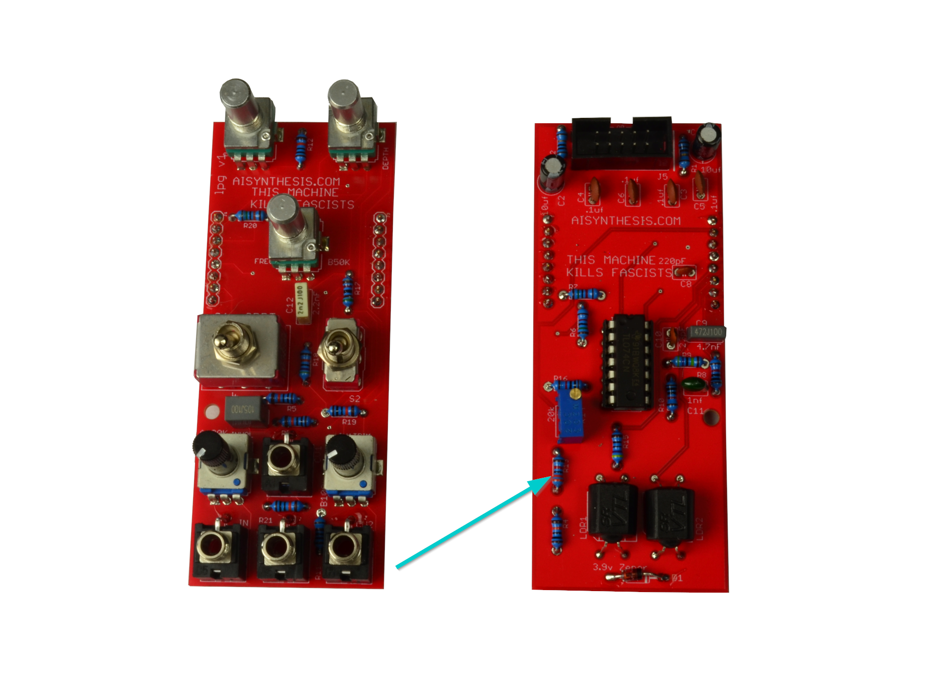
- There is one 33K Resistor at R13.

- There is one 4.7M Resistor at R9.

- Now solder the 51K Resistor at R17.
- There is one 470K resistor at R18.
- There is one 470 ohm resistor at R15. We're done with the Resistors!
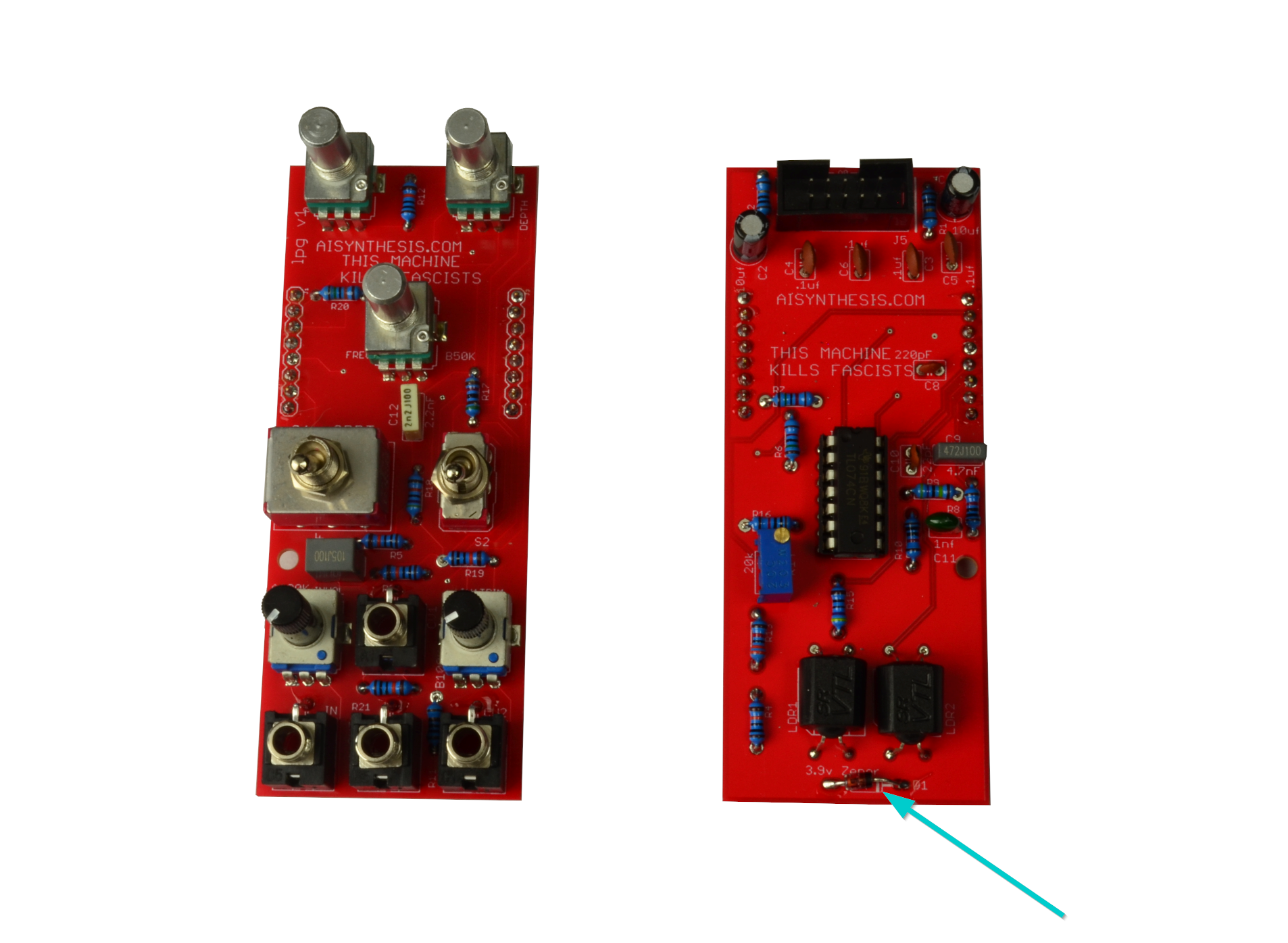
- There is one 1n4730 Diode at D1.
- Now is a good time to at the Shrouded Power Header. Adding it now will allow us to solder other "tall" items without putting pressure on them.
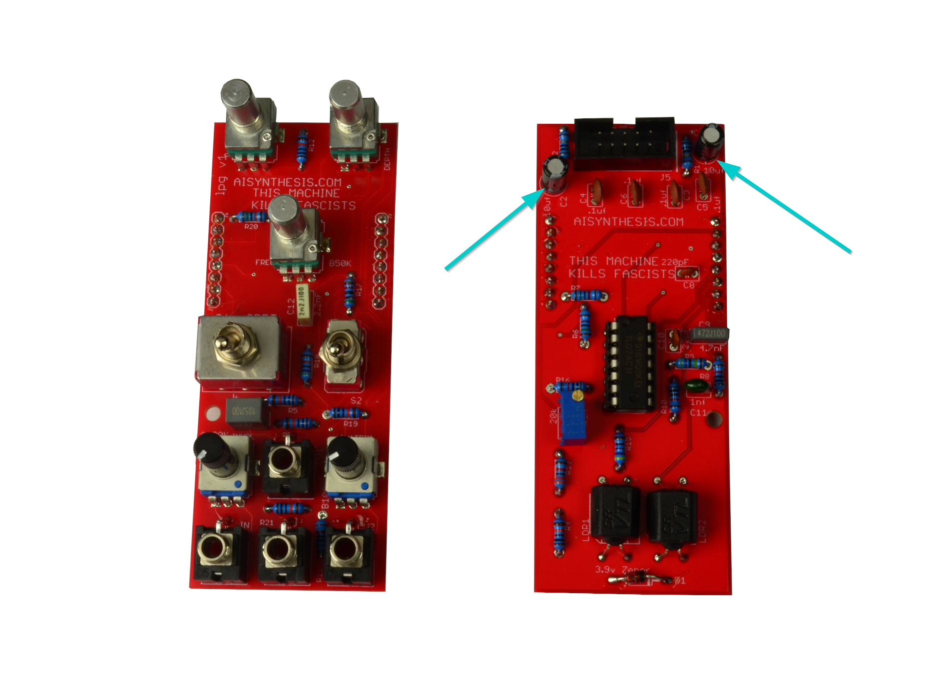
- There are two 10uF Capacitors at C1 and C2 to filter incoming power. These are polarized.
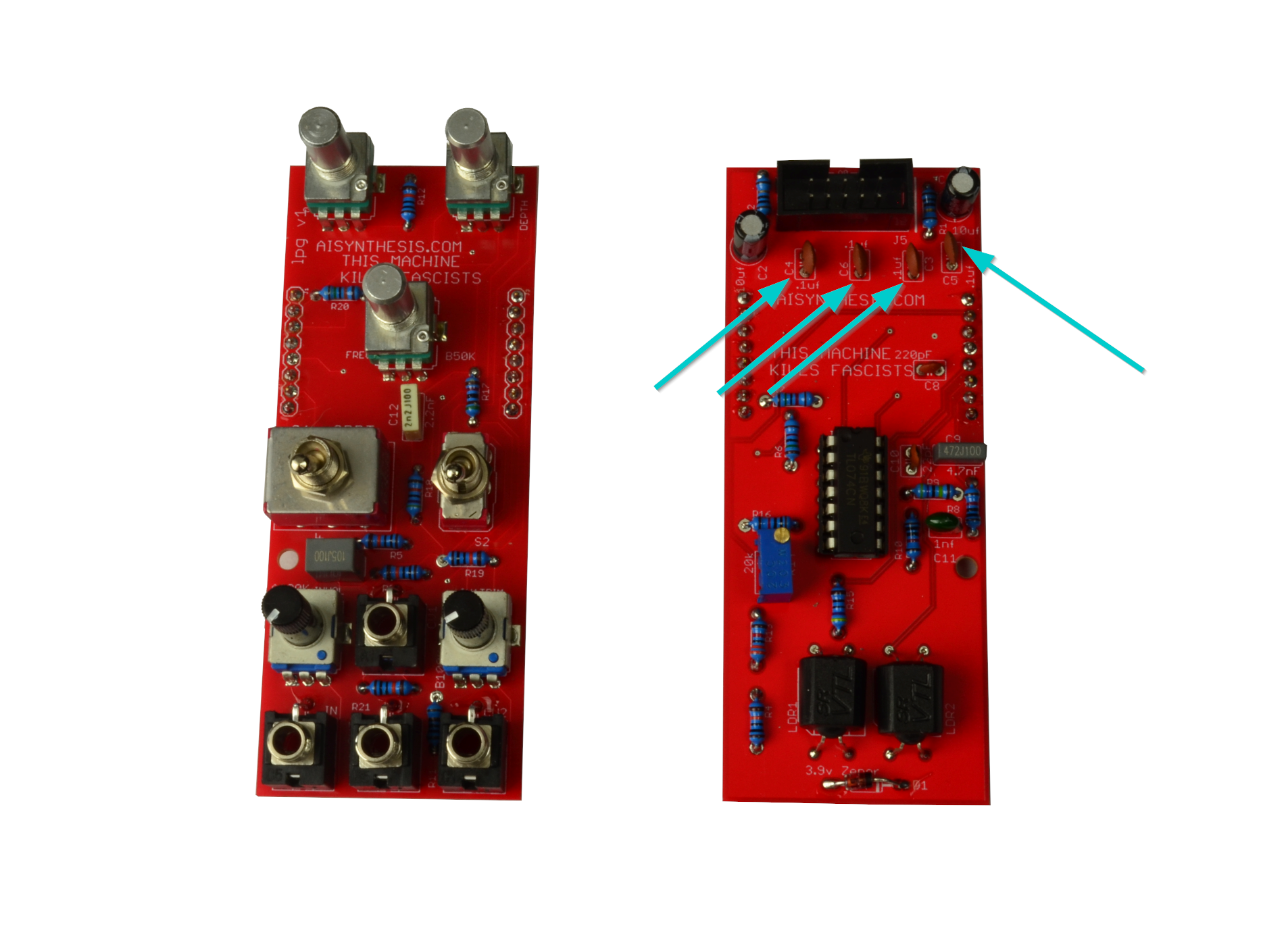
- There are four .1uF capacitors, which are also there to filter power.
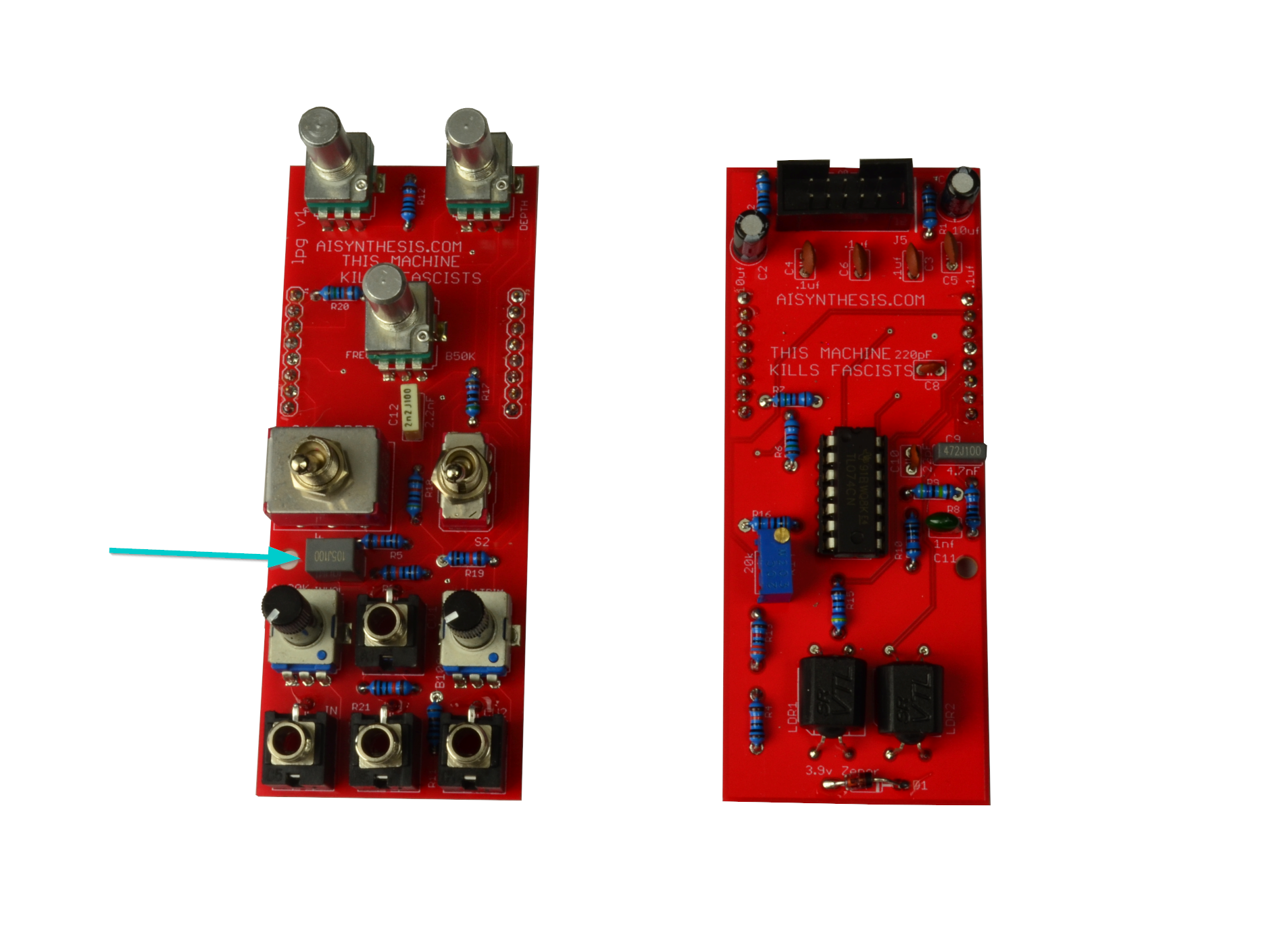
- There is one 1uF non polarized Capacitor at C7.
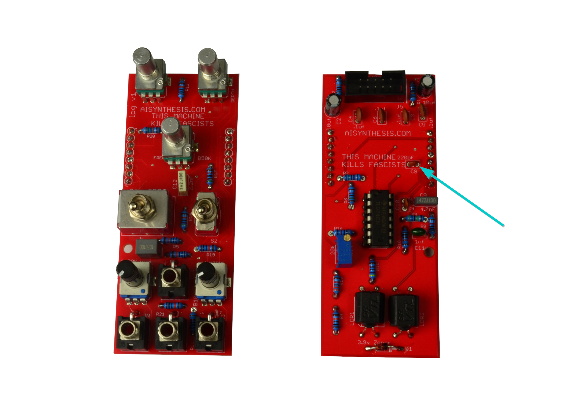
- There is one 220pF capacitor at C8.
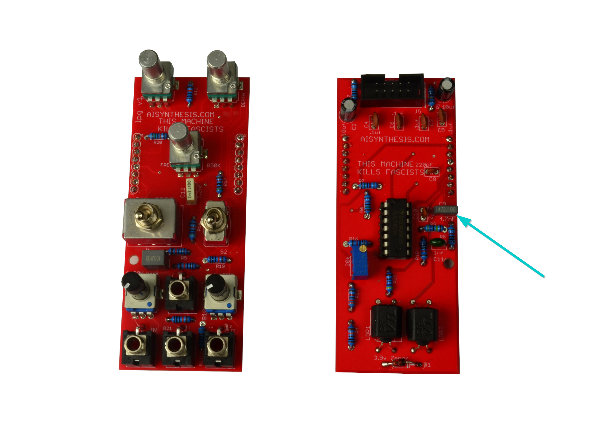
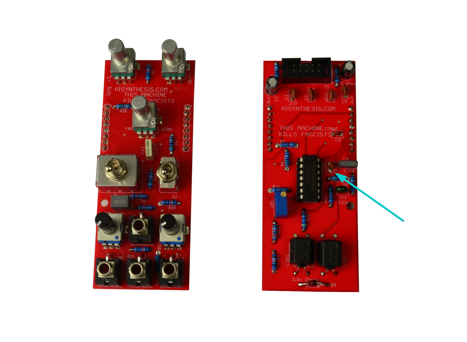
- There is one 4.7nF capacitor at C9.
- There is one 22pF capacitor at C10.
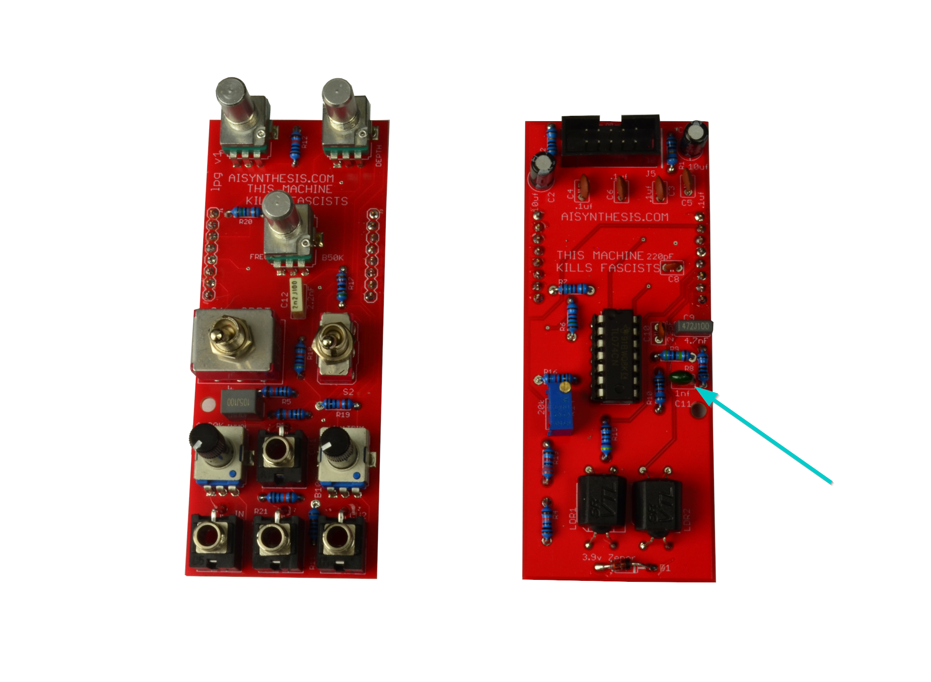
- There is one 1nF capacitor at C11.

- There is one 2.2nF capacitor at C12.
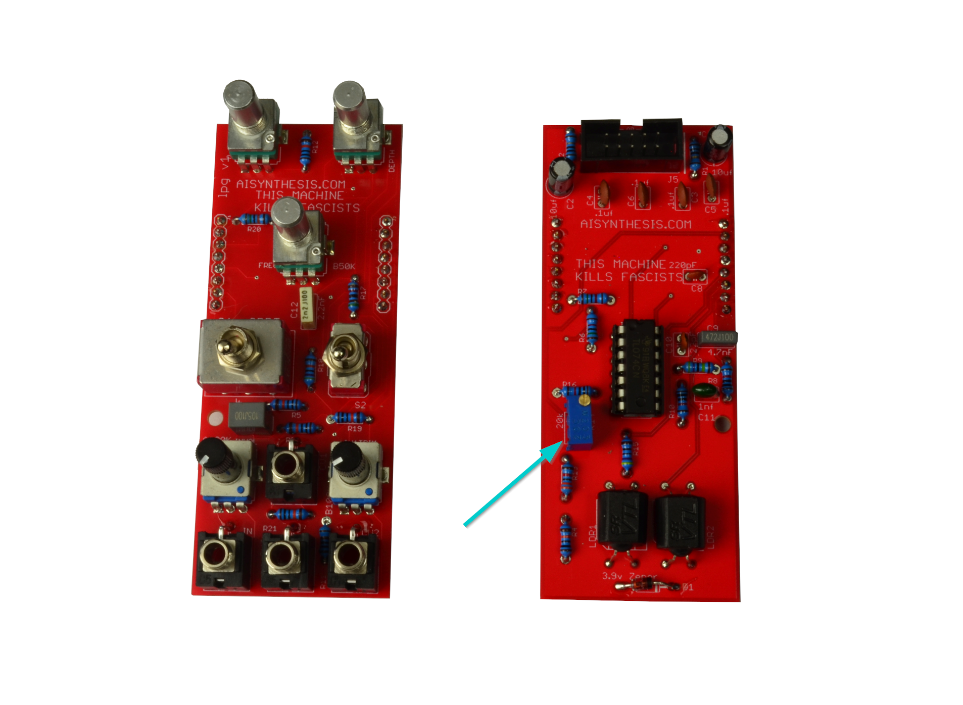
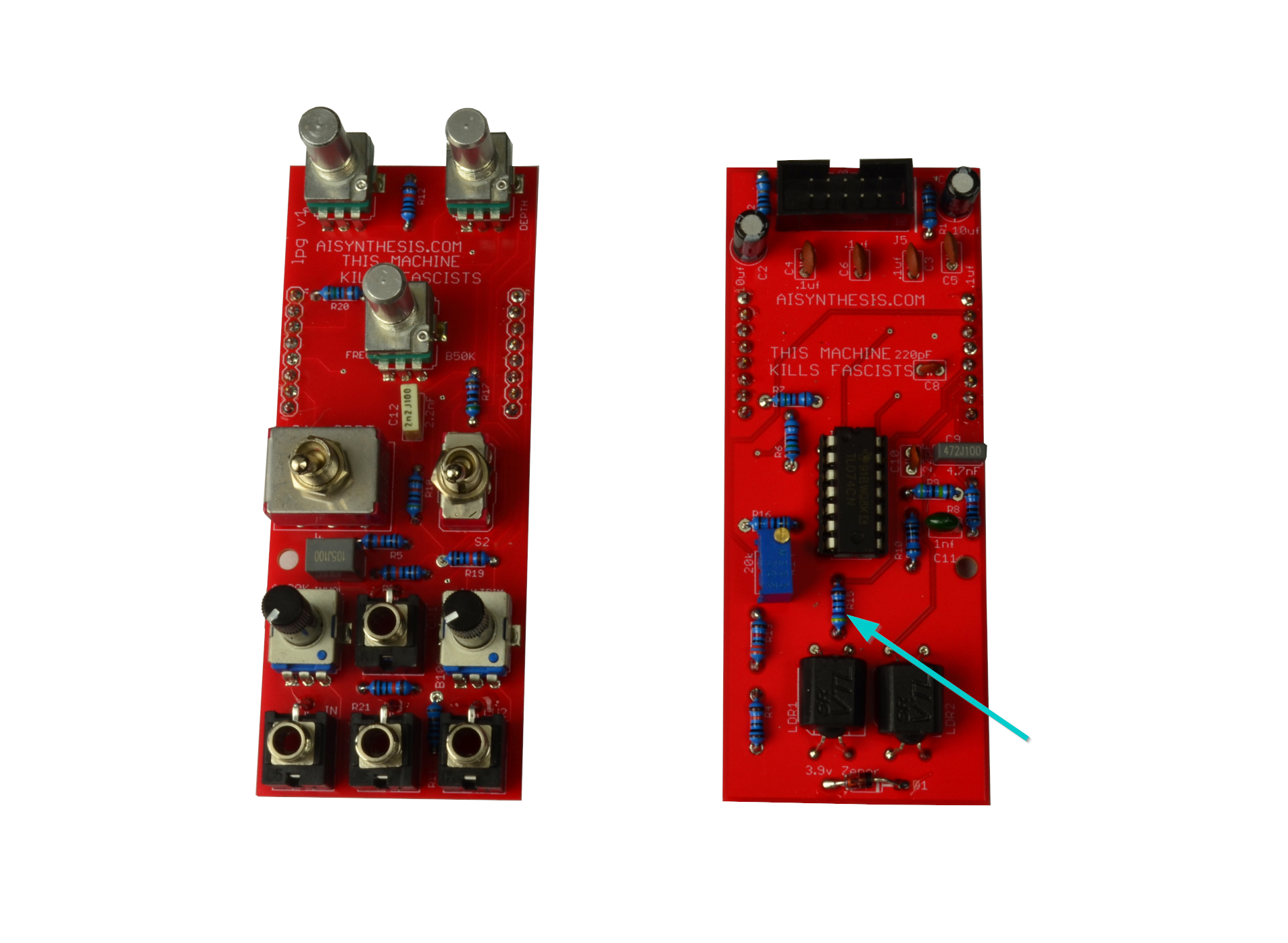
- Now solder the 20k trimmer. This will control the maximum Resonance when in VCF mode.

- Solder the 14 pin IC socket, but don't place the chip just yet. You might want to test power before risking the IC. Ensure that the divot in the socket aligns with the silkscreen to help you ensure that the ICs are placed properly.
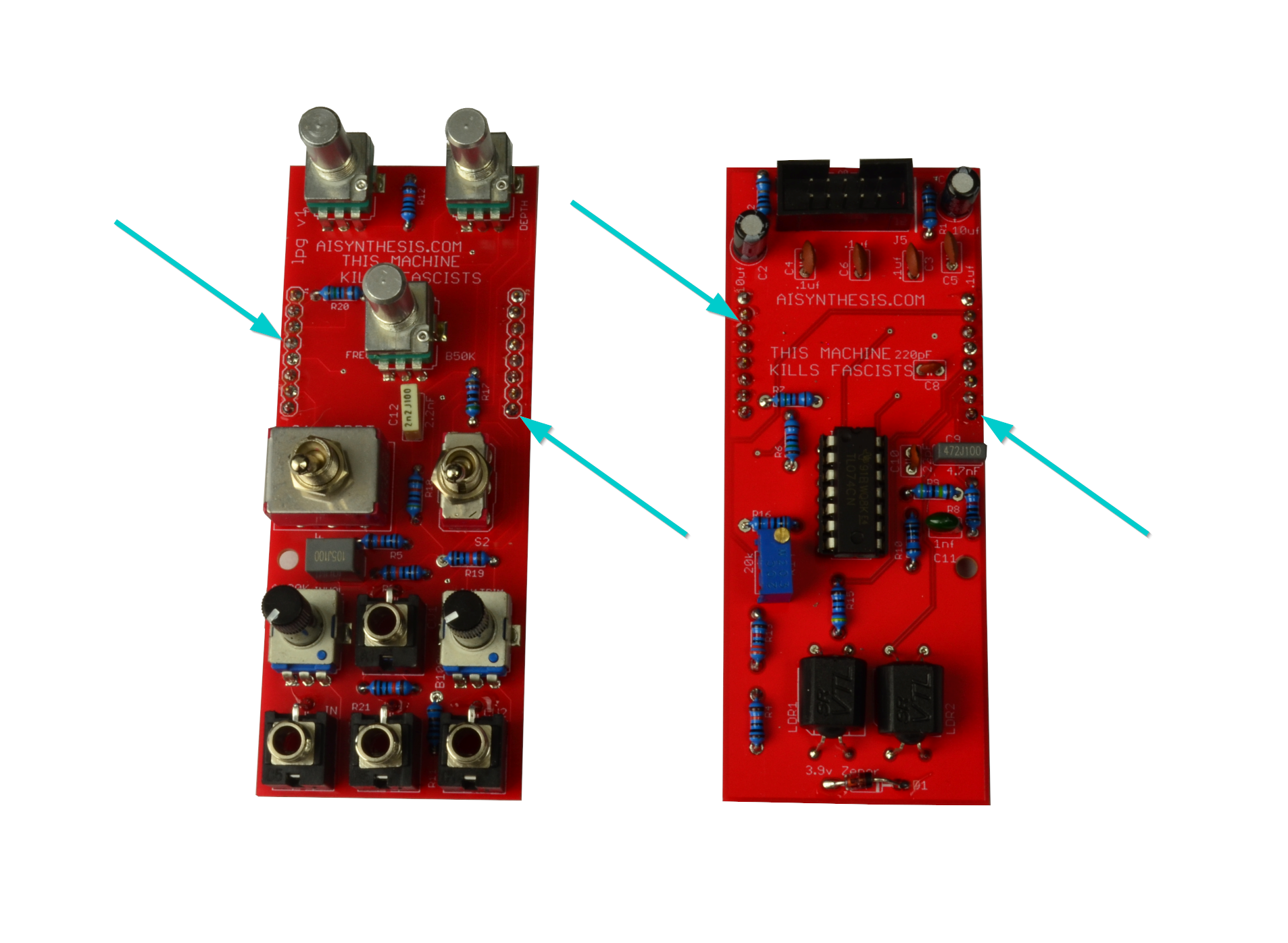
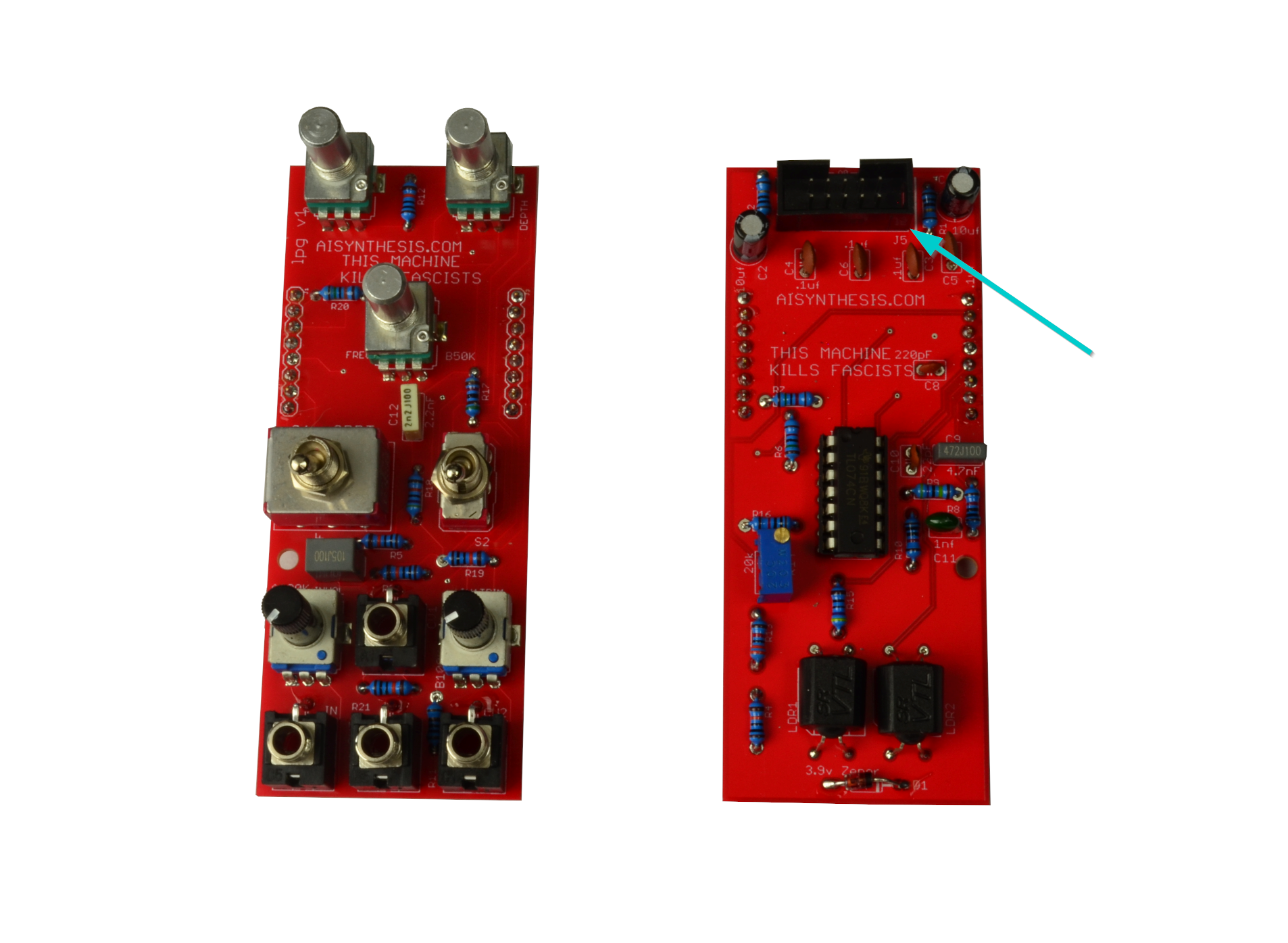
- Now solder 8 pin plug and socket headers that will connect the two PCBs.
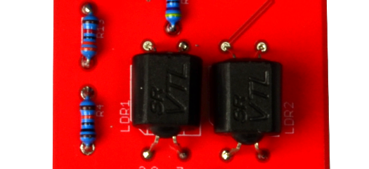
- Now solder the two vactrols. Pay attention to the picture to ensure the alignment is correct.
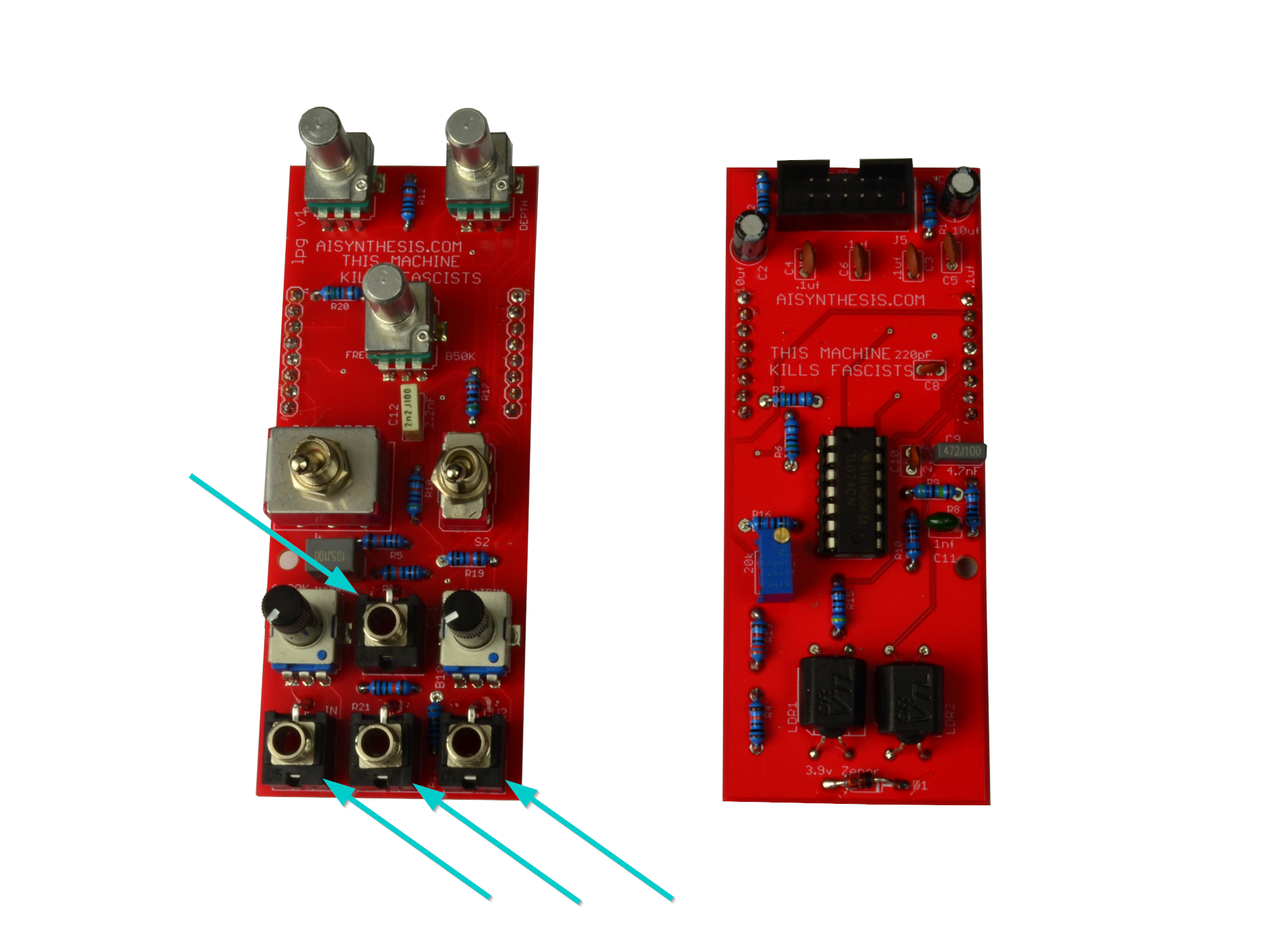
- Now solder the four Jacks. I like to solder the ground lugs from the top of the PCB and then finish below.

- Now solder the two A100K pots. One is a tall trimmer and the other is an Alpha pot.

- Now solder the B100k tall trimmer. This is a simple attenuator for control voltage.
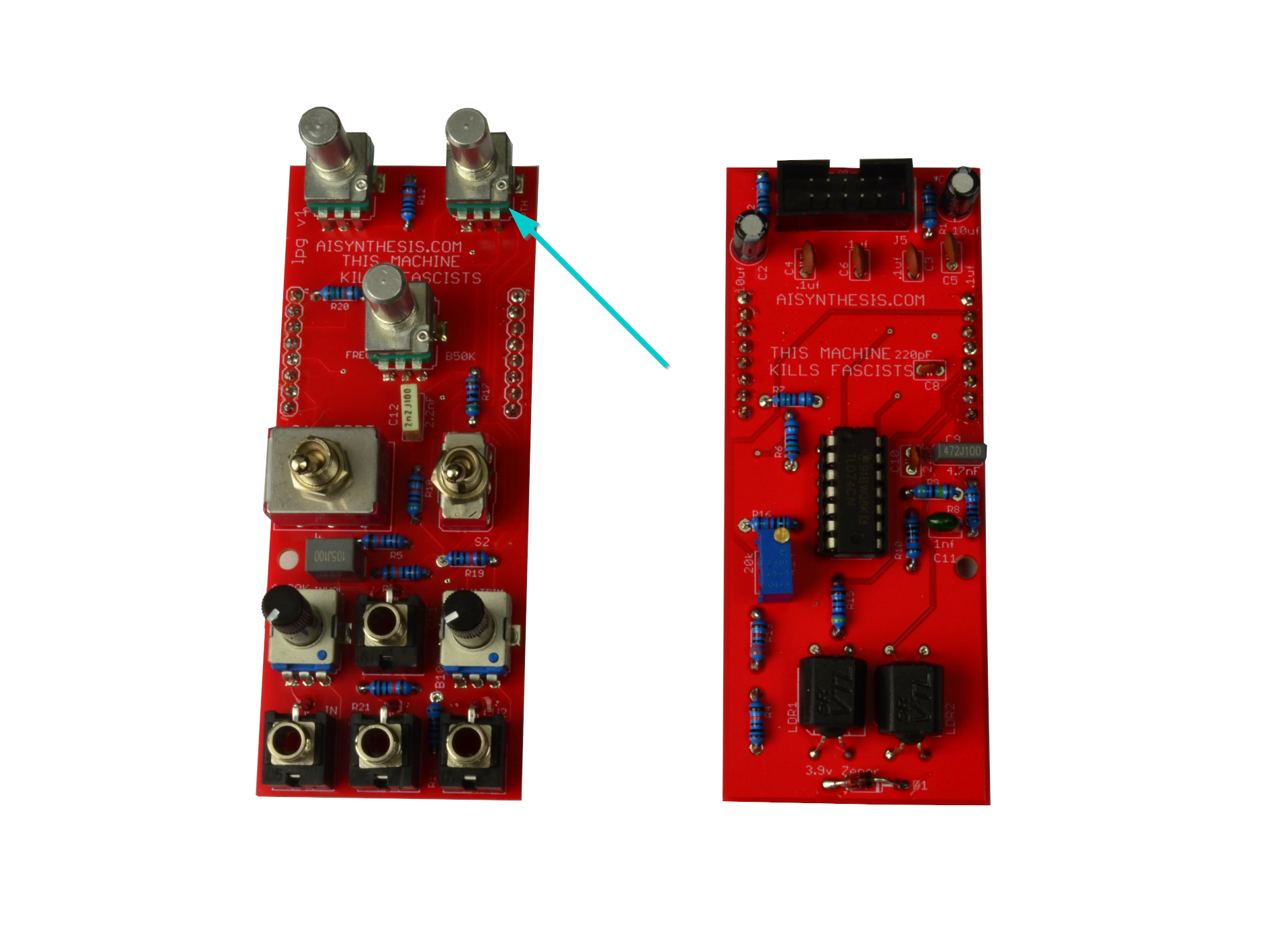
- Now solder the A500K pots. This is the Depth Control.

- Now solder the B50K Potentiometer which is the Level/Cutoff Control.
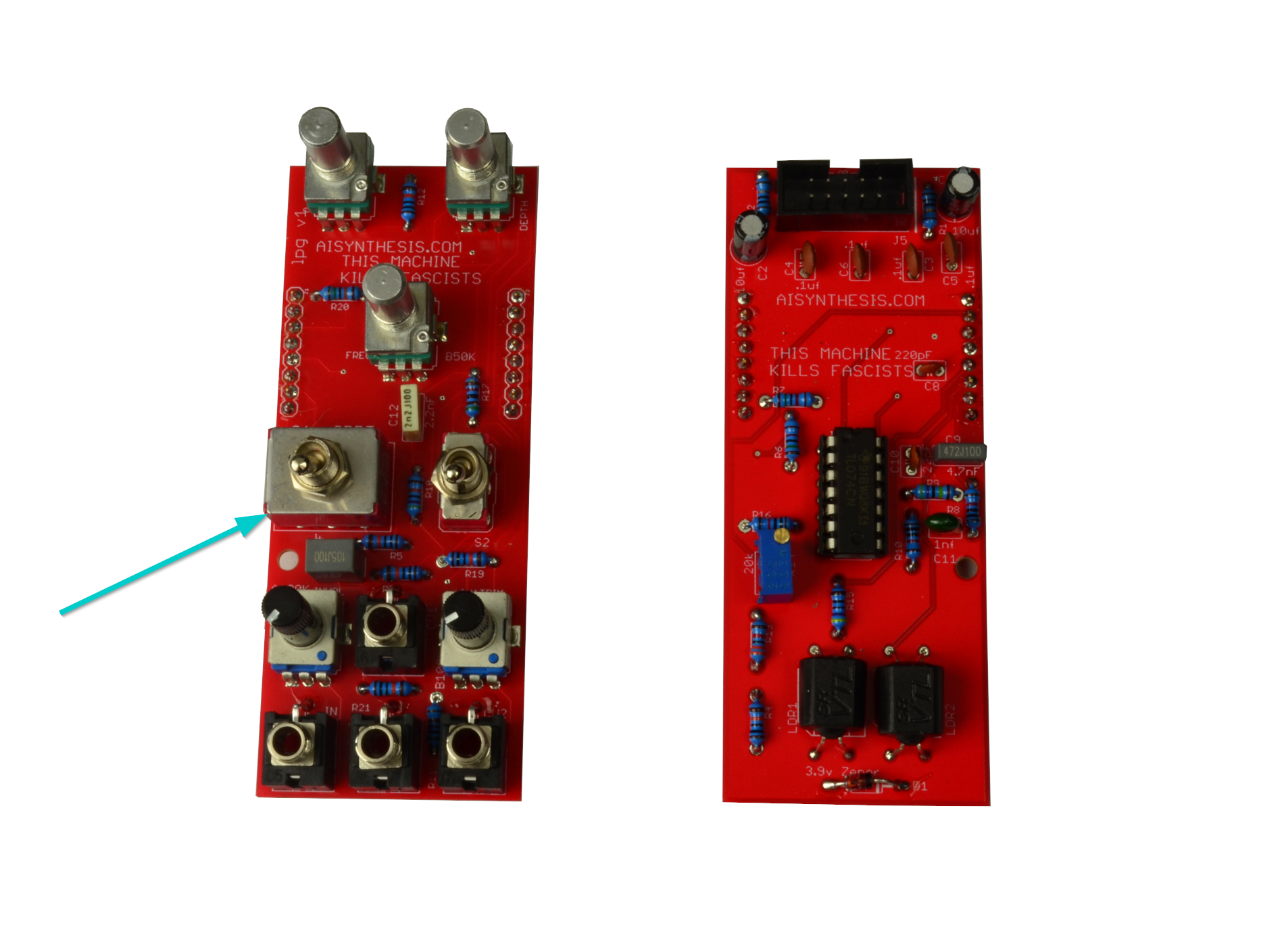
- Now solder the 3PDT switch. Ensure the switch moves up and down (instead of left and right). It's wise to "soft-place" the panel to ensure the switch is straight.
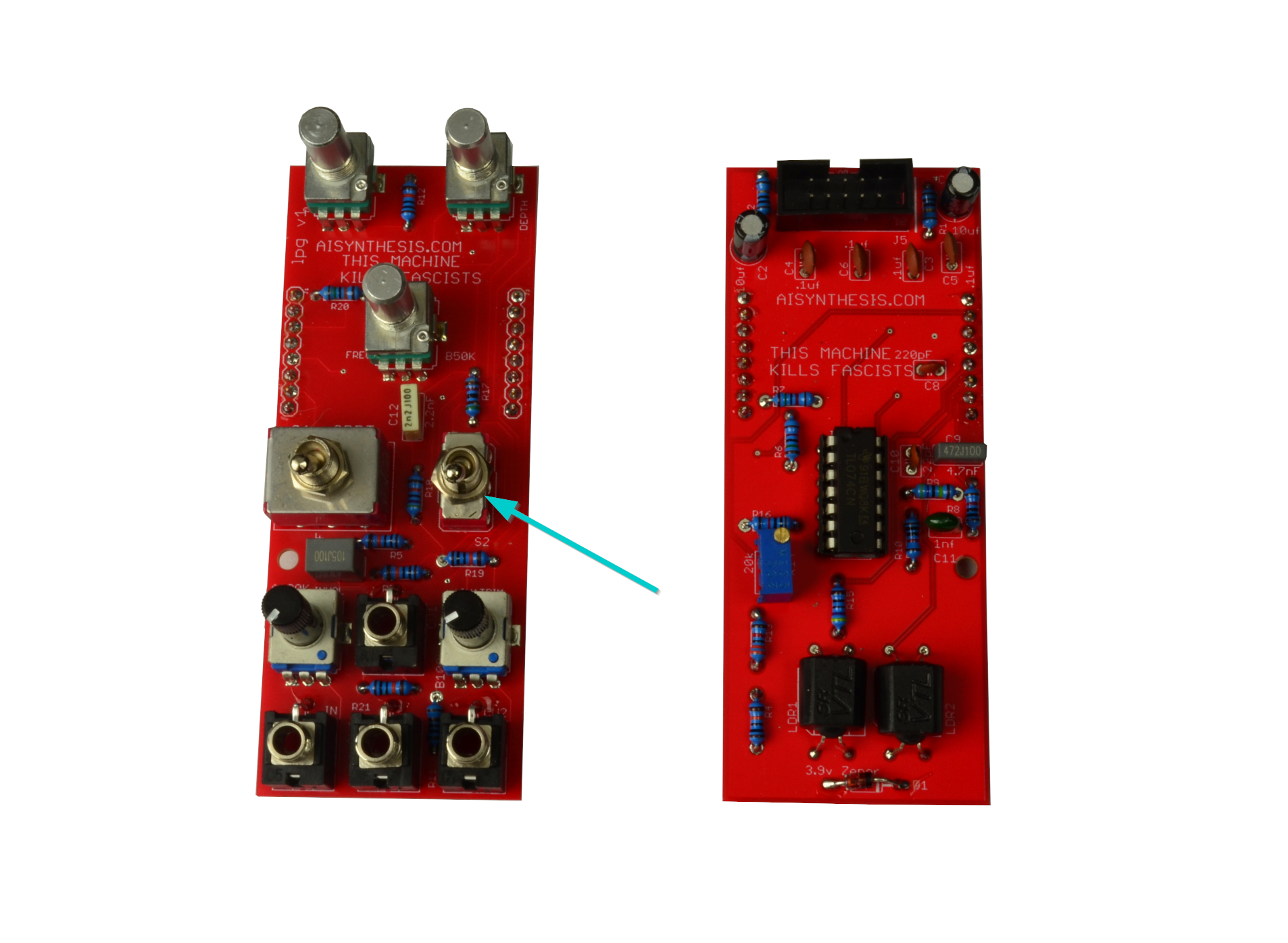
- Now solder the SPDT switch, which turns the Depth control on and off. There is a lot of wiggle room with the switch so it might be good to soft fit the panel and put it over something so the switch hangs straight down and not to the left or right. Normally I throw out the toothed washers that come with these, but you might want to use one as a spacer below the panel - up to you!
- IMPORTANT!!!!! The On-Off-On switches are taller than normal Switches. Do not overtighten any of the nuts and washers for any of the parts, or you may bend the panel. You can also cause the panel to be bent to the right, which causes wear on the plastic pots. The "right way" is to put two toothed washers on the SPDT, making the two switched the same height. From there you can place the panel and put the jack nuts on, but only turn them a few times. There will be a very slight bend to the pcb, but you shouldn't notice it when the module is in your rack. This is a side effect of the taller switch. The only other option was to either remove features or make a weird sub pcb for the switch.
- Now perform a Continuity Test and insert the IC.
Congratulations!
Share your build on Facebook and Instagram!
If you are having any issues at all, please contact me at: https://aisynthesis.com/contact/.