
How to Build the AI106 DIY West Coast Mixer
This is the build guide for the AI106 DIY West Coast Eurorack Mixer Module
Table of Contents
- Resources
- About the AI106 West Coast Mixer
- Tools Needed
- BOM (Bill of Materials)
- Build Guide
1. Resources
2. About the DIY West Coast Eurorack Mixer
This DIY West Coast Eurorack Mixer uses transistors and other discrete components to bring 1960s "West Coast" mixing technology to your Eurorack system. This mixer will add gain and harmonics as volume is increased, resulting in warm distortion, rectification, and even clipping when pushed.
3. Tools Needed
- Soldering Iron: Cheap
or Nice
- Solder
- Soldering Tip Cleaner
- Micro-Shear Flush Cutter
For testing and Calibration:
4. BOM
| Category | Part | Quantity | Designation |
|---|---|---|---|
| Capacitor | .1uF Capacitor | 1 | C 1 |
| Capacitor | 10uF Capacitor | 1 | C3 |
| Capacitor | 5pF Capacitor | 1 | C4 |
| Capacitor | 100uF Capacitor | 2 | C5-6 |
| Hardware | Shrouded Power Header | 1 | Power |
| Hardware | Jack | 4 | In 1, 2, 3, Out |
| Nut | Nut | 4 | |
| Potentiometer | 9mm Alpha Potentiometer A100K | 4 | P1-3, Master |
| Resistor | 68K Resistor | 3 | R1-3 |
| Resistor | 15K Resistor | 2 | R4, 7 |
| Resistor | 2.2K Resistor | R5 | |
| Resistor | 1.5K Resistor | 1 | R6 |
| Resistor | 1K Resistor | 1 | R8 |
| Resistor | 330 Ohm Resistor | 1 | R9 |
| Resistor | 220 Ohm Resistor | 1 | R10 |
| Resistor | 10K Resistor | 1 | R11 | Transistor | 2n3904 | 2 | T1, 2 |
5. Build Guide
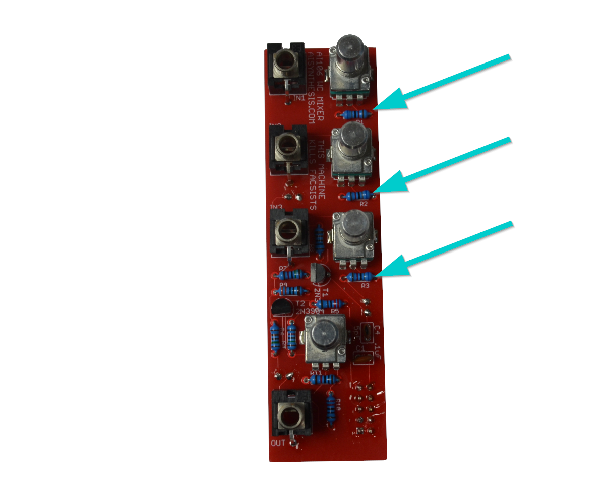
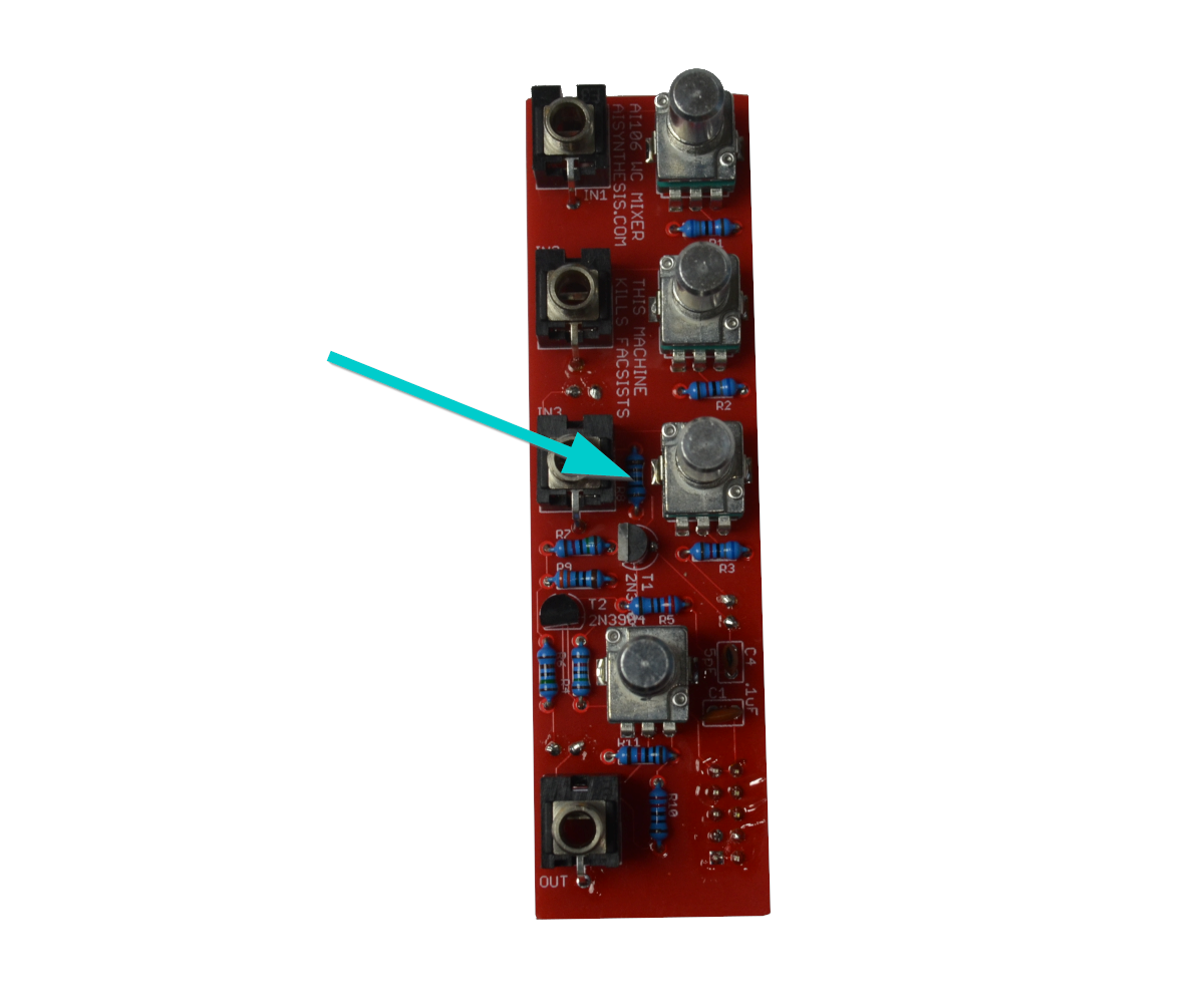
- As usual, we solder from "low items to high items." First solder the three 68k resistors.
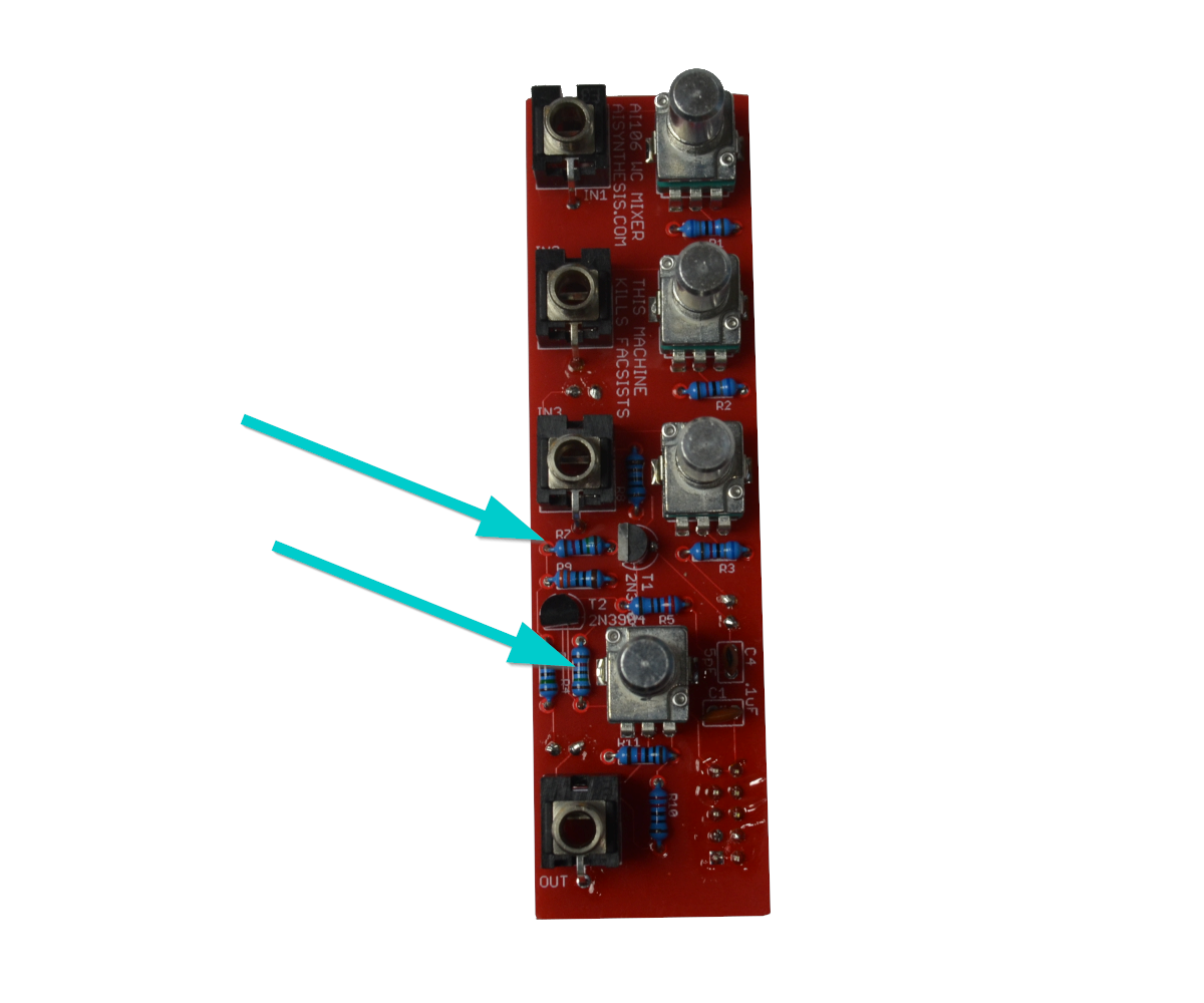
- Now solder the two 15k resistors.
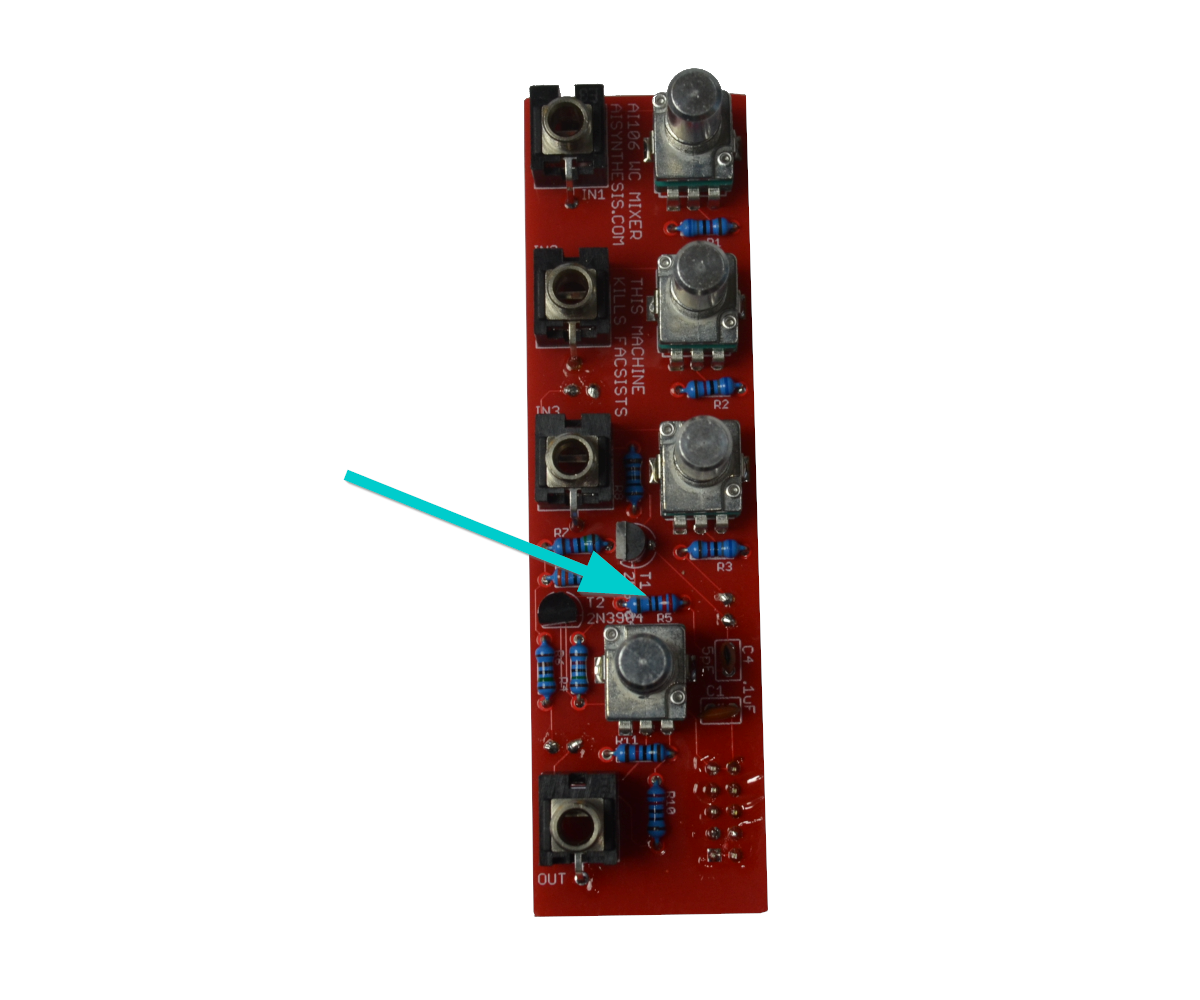
- Now solder the 2.2K resistor.
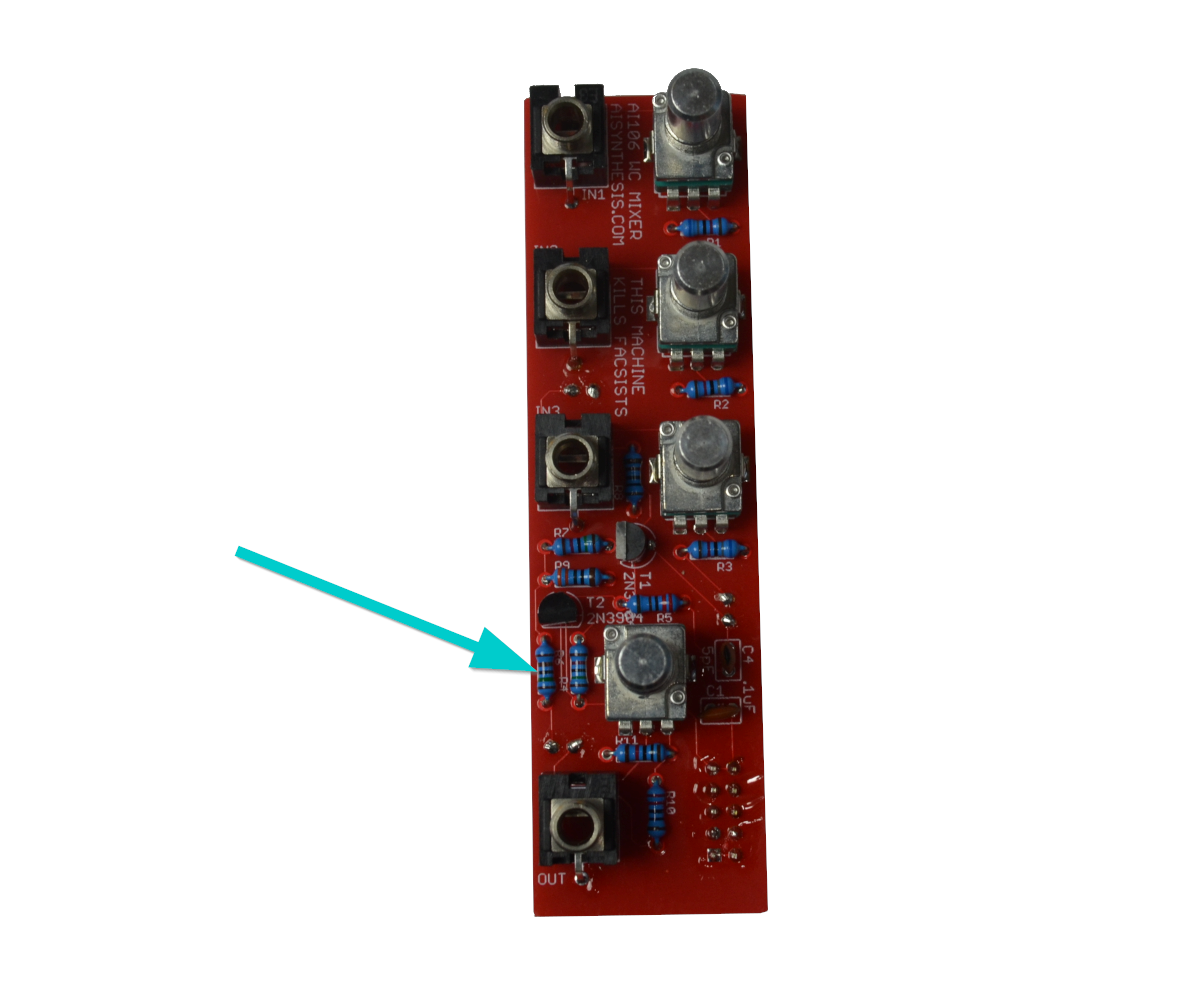
- There is one 1.5K Resistor at R6.
- There is one 1K Resistor at R8.
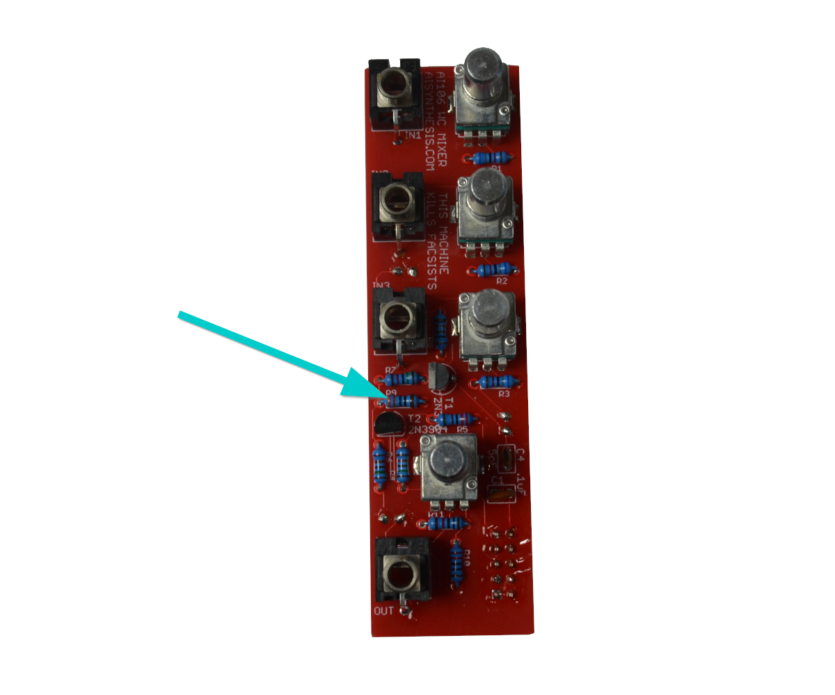
- Now solder the 330 Ohm Resistor at R9.
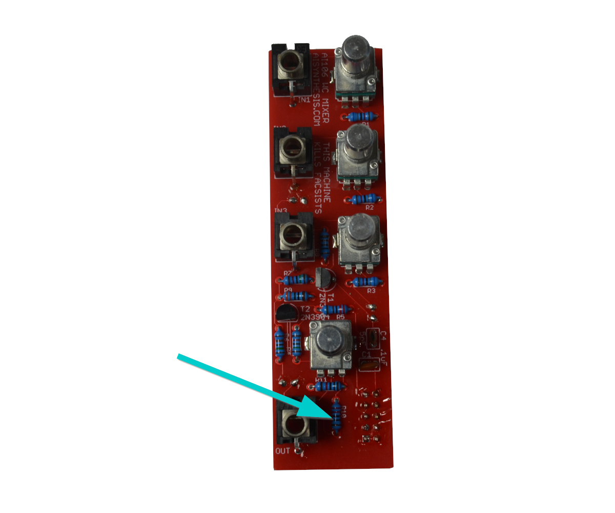
- There is one 220 Ohm Resistor at R10.
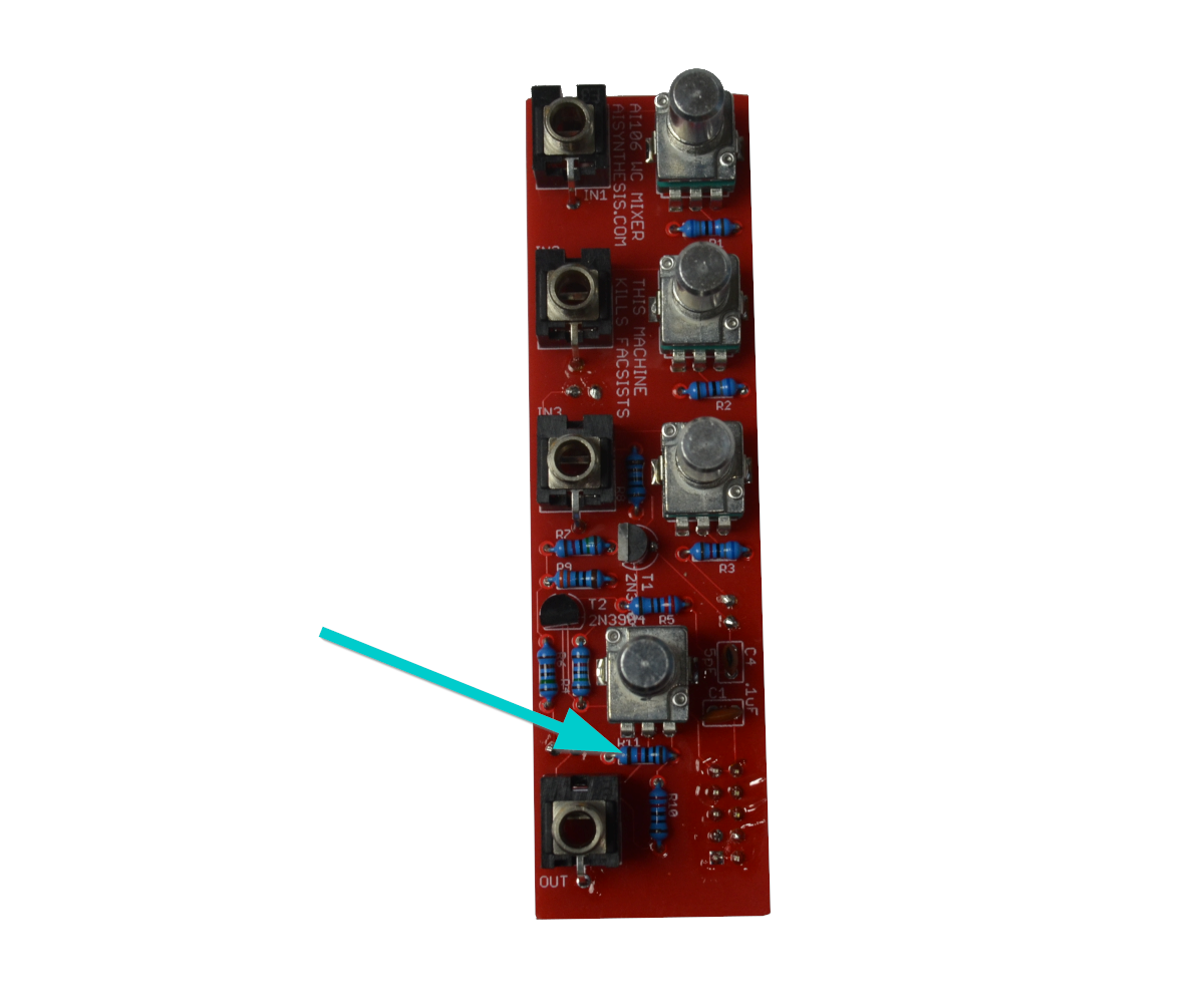
- There is one 10K Resistor at R11.
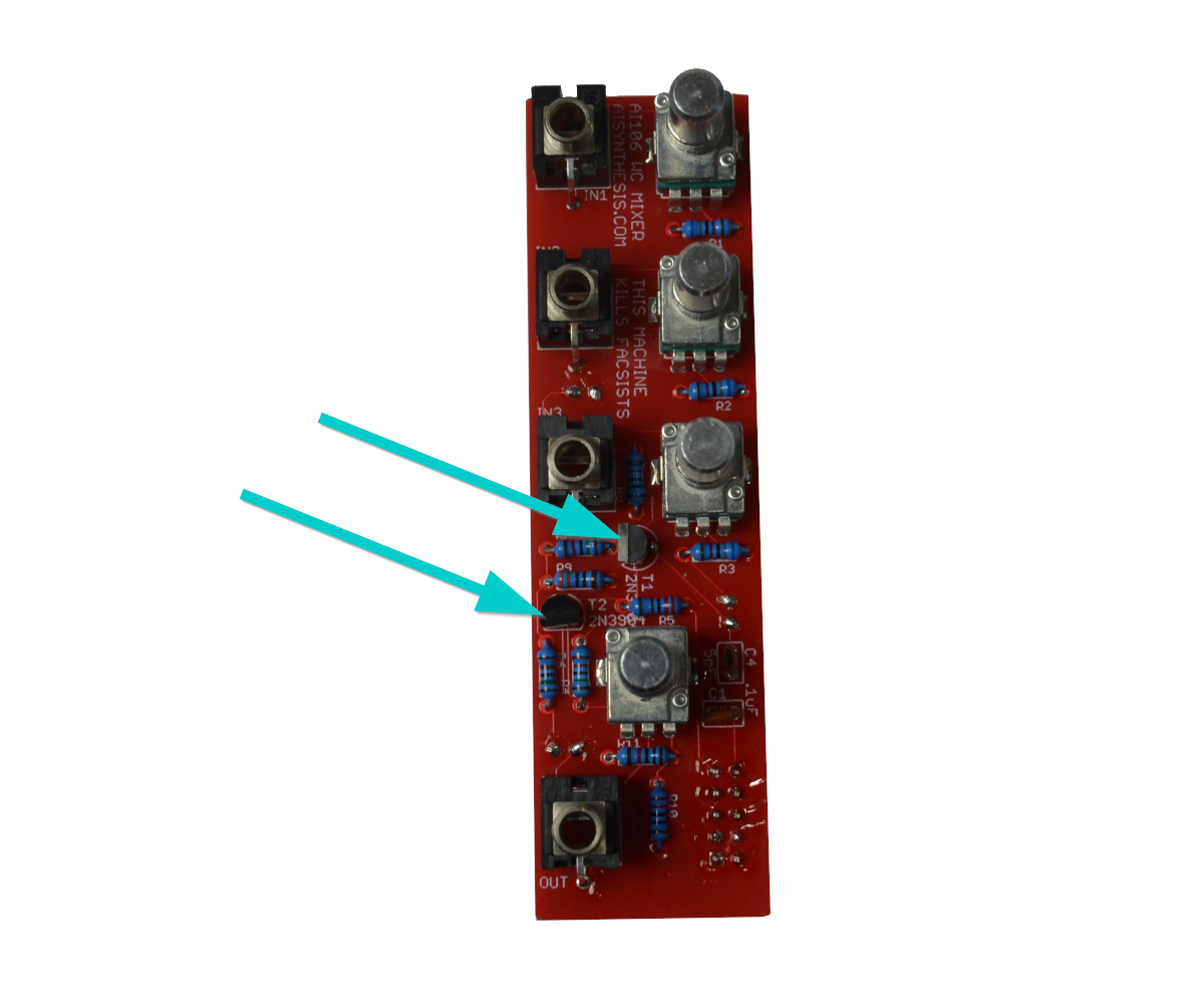
- Now solder the two 2n3904 Transistors at T1 and T2.
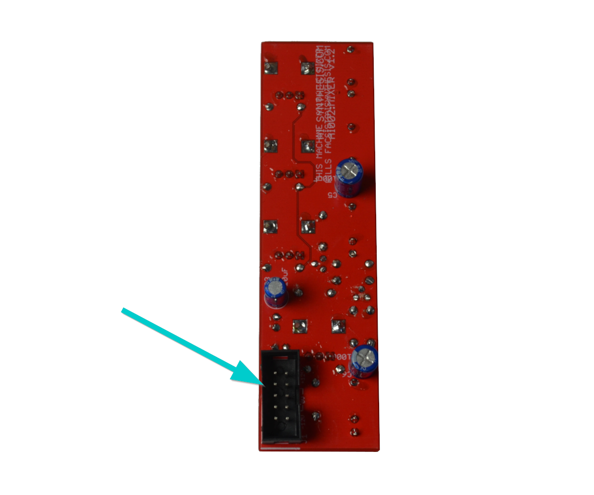
- Now solder the shrouded power header. Solder one pin first, then reflow while you ensure the Power Header is flat against the PCB. Make sure the alignment matches the picture.
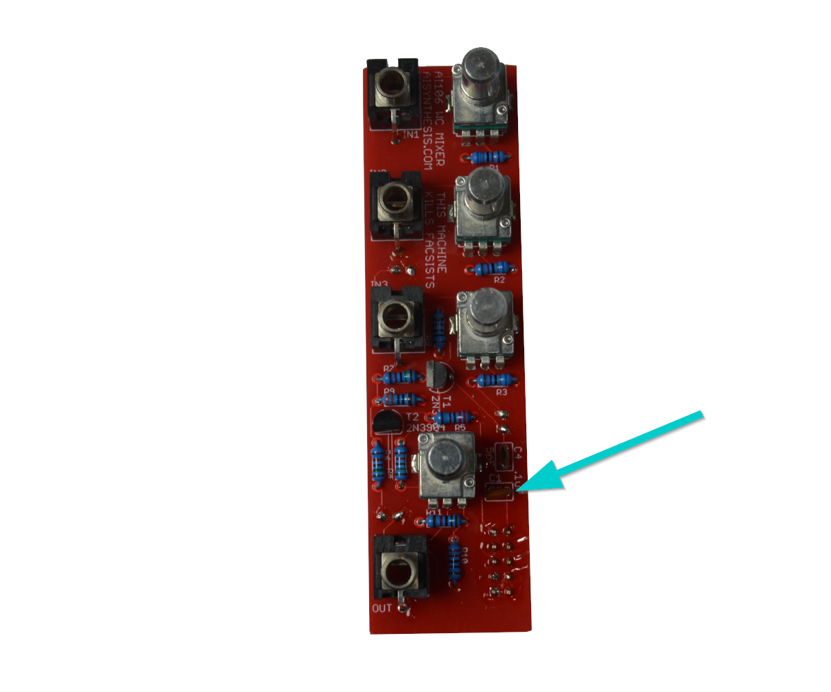
- There is 1 .1uF Capacitor at C1.
- There is 1 10uF Capacitor at C3. Mind the polarity.
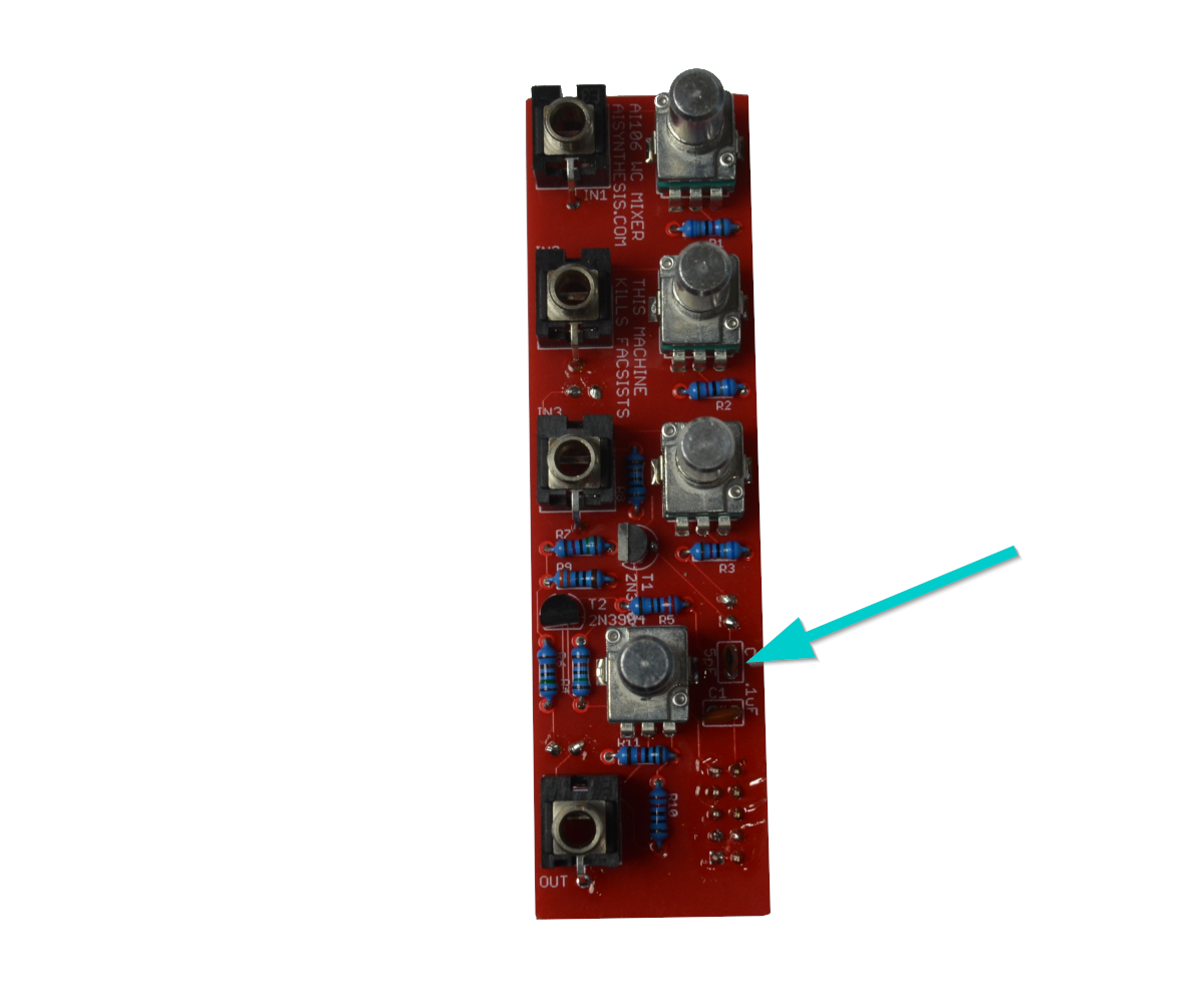
- There is 1 5pF Capacitor at C4.
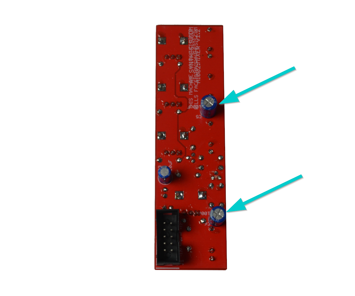
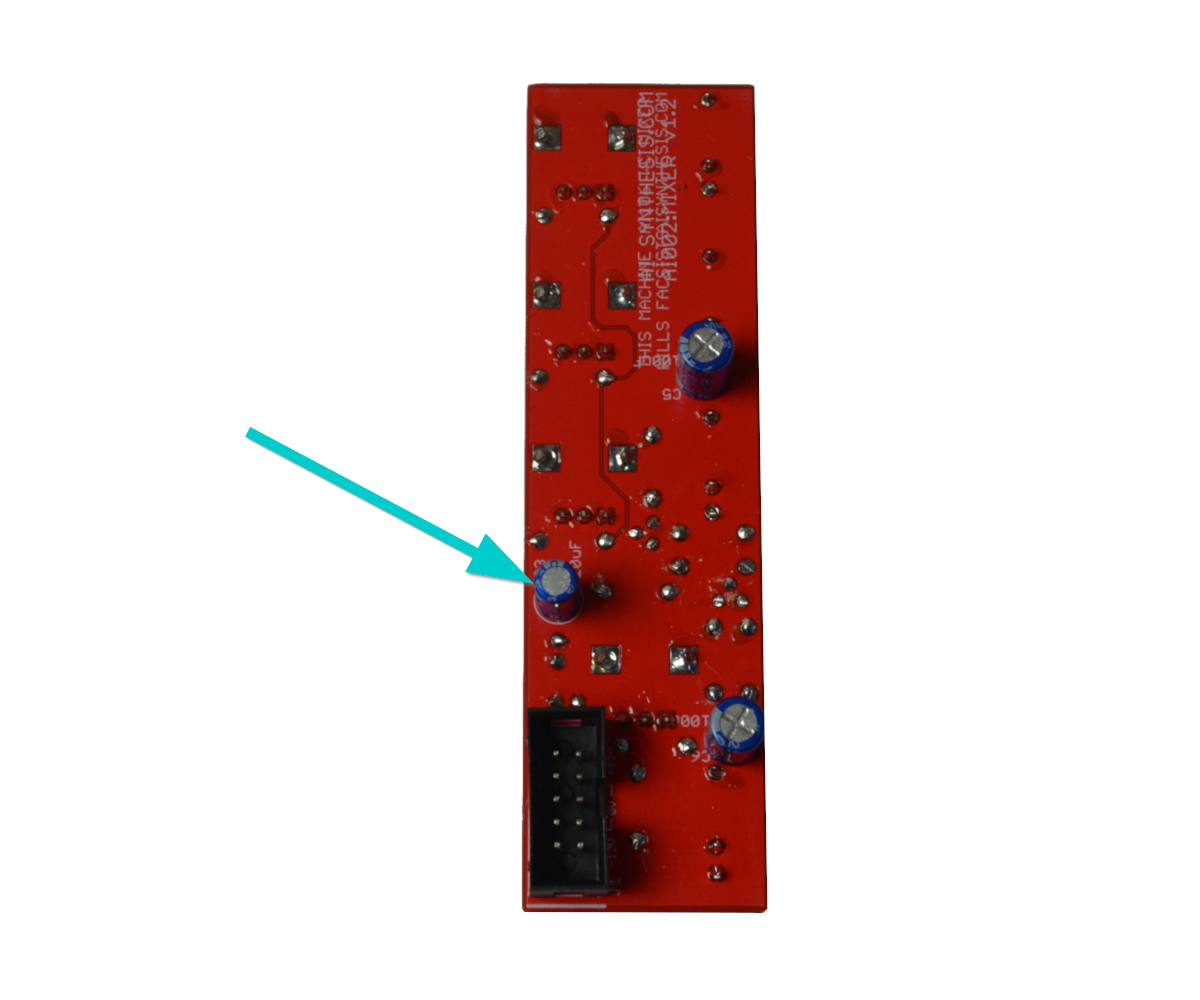
- There are 2 100uF Capacitors at C5 and 6. Mind the polarity.
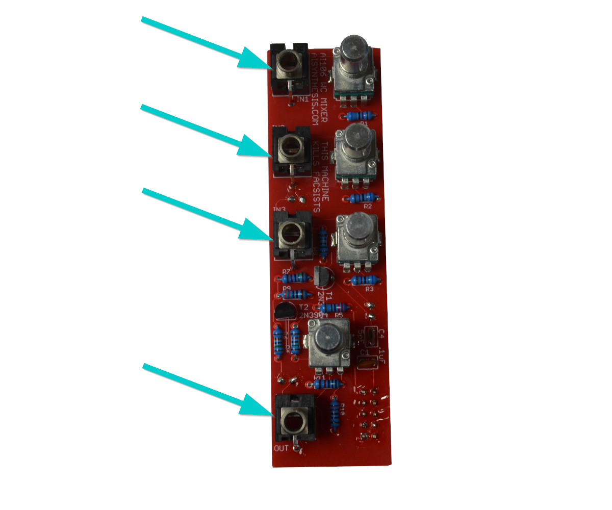
- Now that we are done with those we can solder in the jacks. I like to start with the ground lugs on the top side of the PCB to ensure they are flat, and then turn it over to finish them.
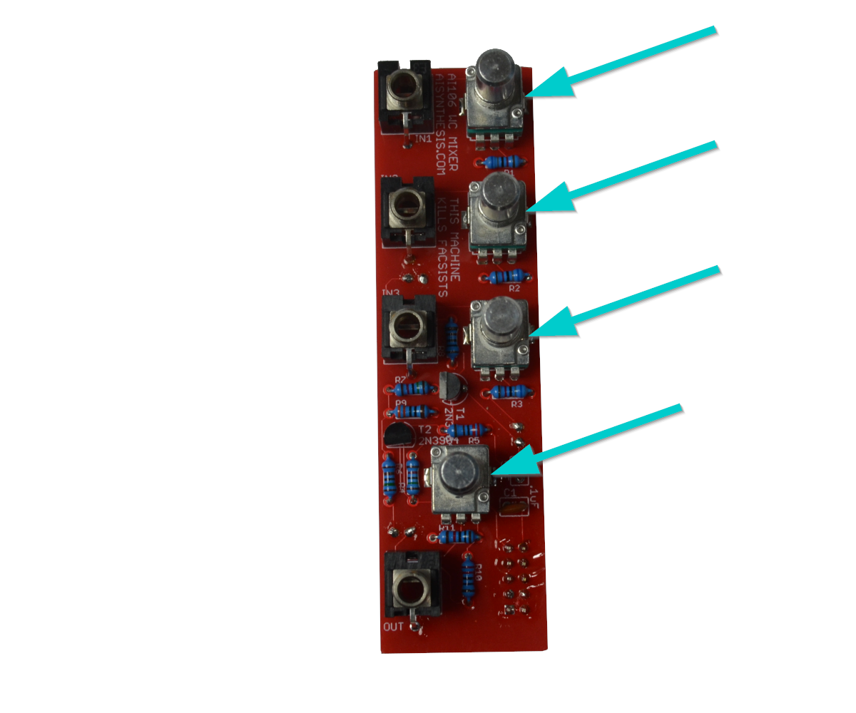
- Now solder in the four A100k Metal pots.
- Now perform a Continuity Test and power on.
Congratulations!
Share your build on Facebook and Instagram!
If you are having any issues at all, please contact me at: https://aisynthesis.com/contact/.