
AI024 Eurorack DIY X Filter Kit Build Guide
This is the build guide for the AI024 Eurorack DIY X Filter Kit Build Guide DIY Kit
Table of Contents
- Resources
- About the Eurorack AI024 DIY X Filter
- Tools Needed
- BOM (Bill of Materials)
- Build Guide
1. Resources
2. About the Eurorack AI024 DIY X Filter
If you are new to DIY electronics, this is the second module you should build. The first module, the AI001 Multiple is ideal for beginners, as it teaches how to solder and signal flow. The AI002 Mixer familiarizes you with common electronic components, and is powered.
The AI024 Eurorack X Filter brings the clean, classic, creamy filtering of classic 80s synths to Eurorack. It uses the same four pole analog filter topology found in classic synths like the Crumar Spirit, the Digisound-80 Modular System, Elka Synthex, Fairlight CMI II/IIx, LinnDrum, Oberheim,PPG Wave, Sequential Circuits synths, and many more.
3. Tools Needed
- Soldering Iron: Cheap
or Nice
- Solder
- Soldering Tip Cleaner
- Diagonal Cutters
- Micro Shears
- Precision Screwdriver Set
4. BOM
| Category | Part | Quantity |
| Capacitor (Electrolytic) | 10uF | 3 |
| Capacitor | .1uF | 4 |
| Capacitor | 330pF | 4 |
| Diode | 1n4148 | 1 |
| Diode | 1N5817 | 2 |
| Hardware | 6 pin Sockets | 2 |
| Hardware | Socket Plugs | 1 |
| Hardware | 2x5 Power Header | 1 |
| Hardware | Jacks | 5 |
| Hardware | Nuts | 5 |
| Hardware | 18 Pin IC Socket | 1 |
| Hardware | 14 Pin IC Socket | 1 |
| IC | TL074 | 1 |
| IC | Alfa 3320 | 1 |
| Potentiometer | B10K Pot | 2 |
| Potentiometer | B10K Tall Trimmer | 2 |
| Resistor | 91K | 6 |
| Resistor | 220K | 4 |
| Resistor | 100K | 16 |
| Resistor | 1.8K | 5 |
| Trimmer | 25K Trimmer | 1 |
Build Guide
- First, gather your parts together, and snap the two PCBs in half in order to make two PCBs.

- In general with DIY electronics, we want to build “low to high.” “Low to High” means soldering items in reverse order of height, as it is easier to manipulate smaller items when there aren’t taller things to get in the way. In this case, it means starting with the resistors. Start by soldering the two 1N5817 Diodes at D1 and D2. The 1n5817 Diodes must be put in the correct orientation.
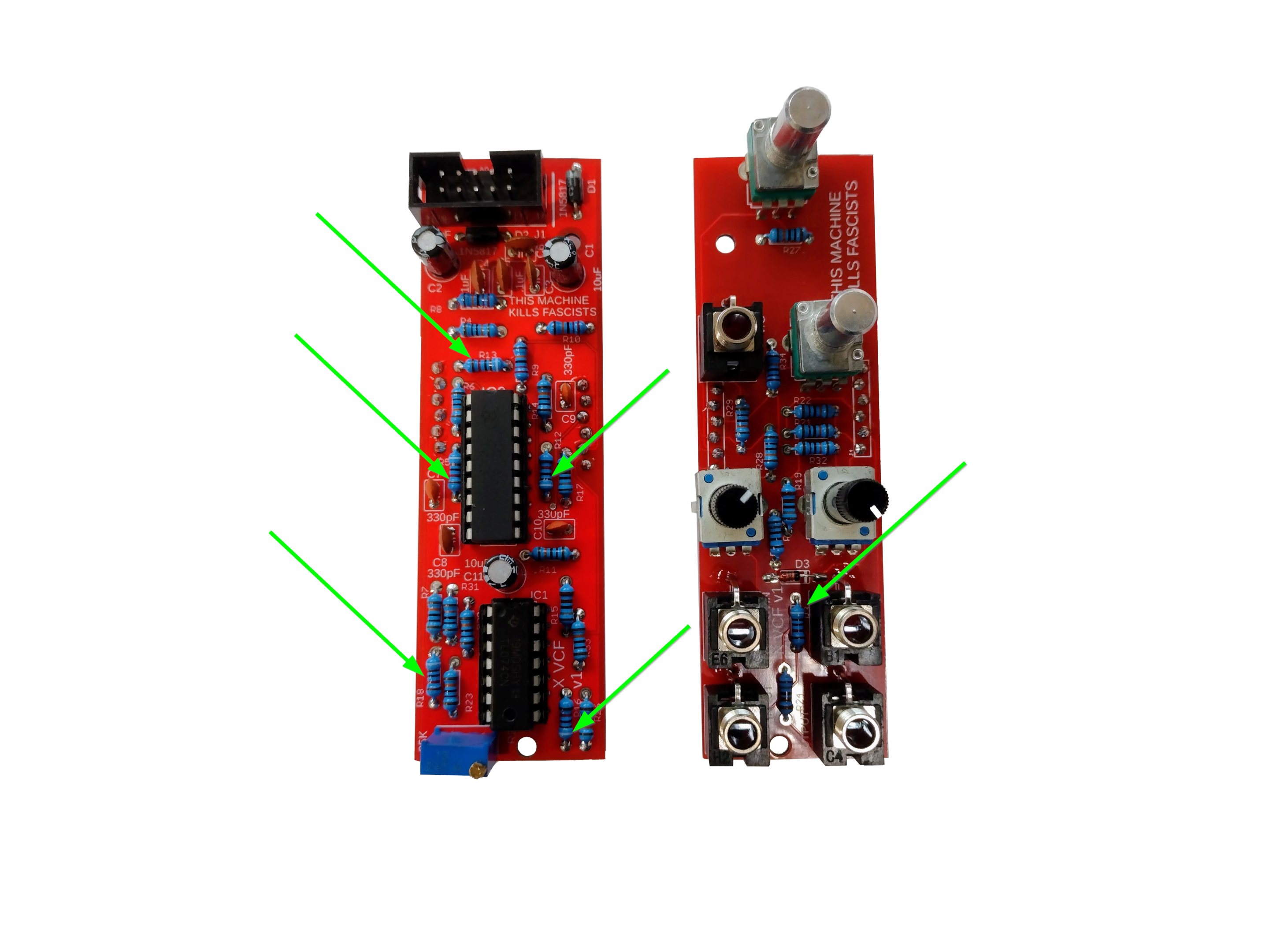
- After that move on to the six 91K resistors.

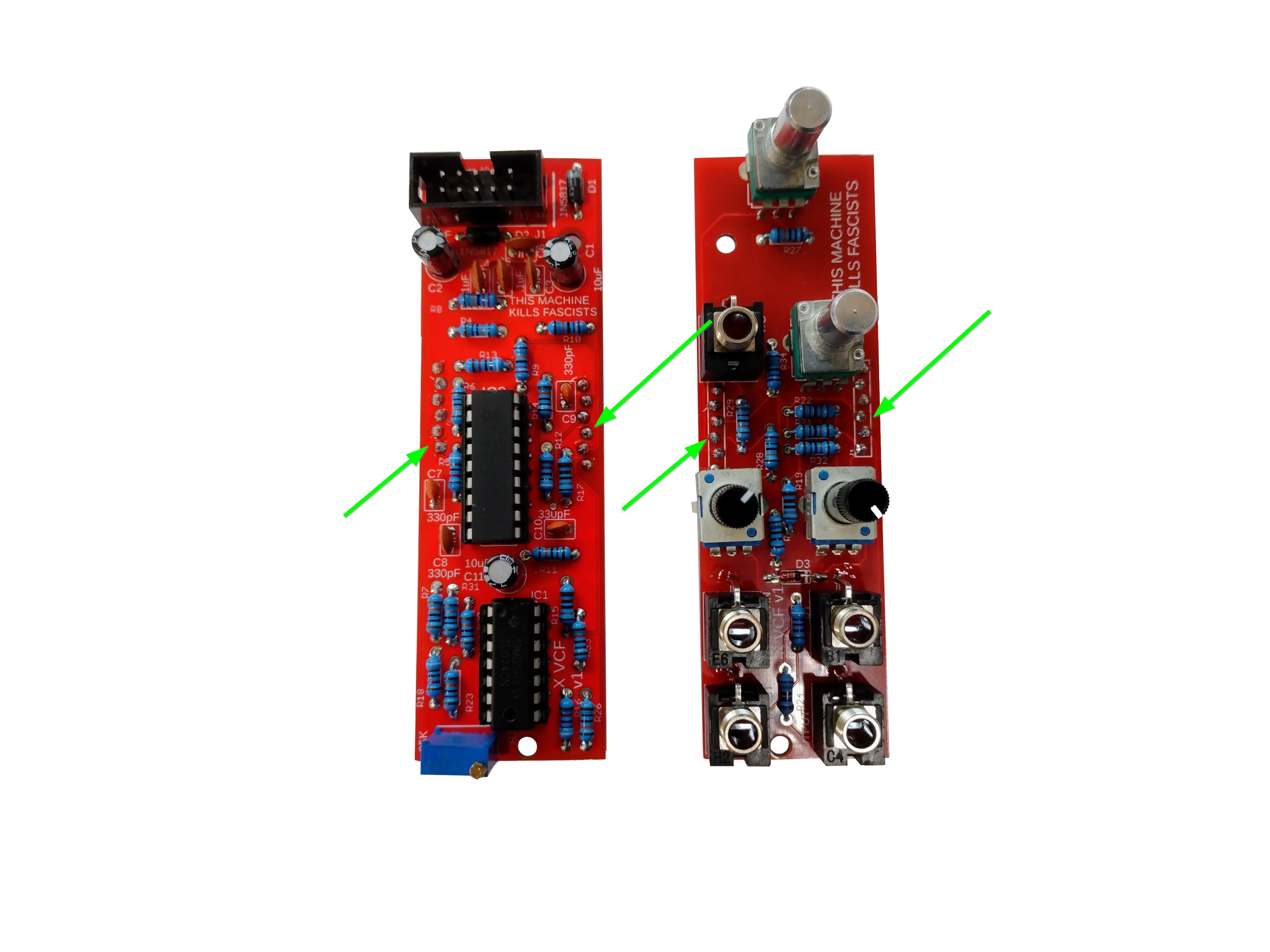
- There are four 220K resistors.
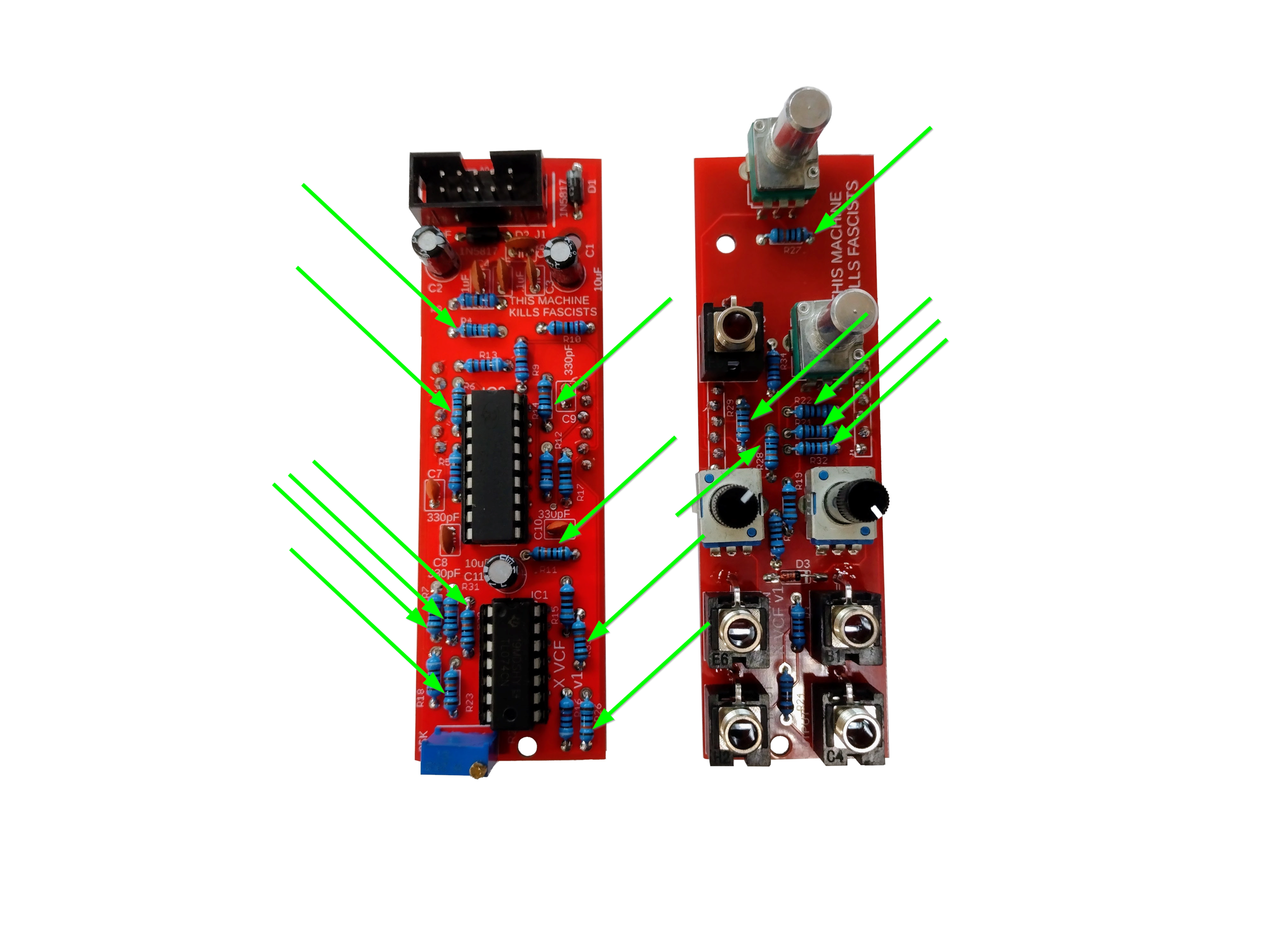
- There are sixteen 100k resistors.
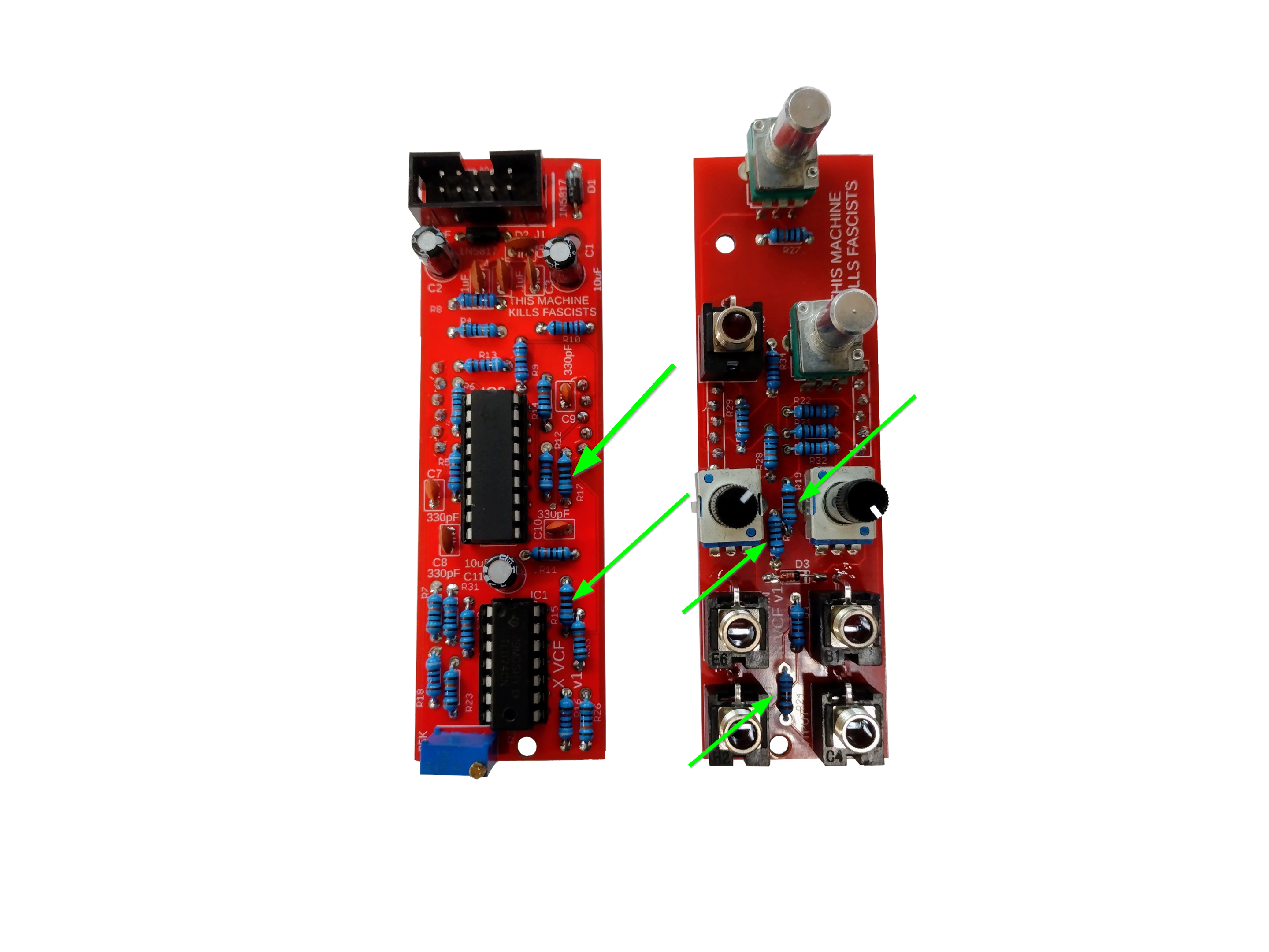
- There are five 1.8K resistors.
- There are two sets of 6 pin sockets and 6 pin plugs.
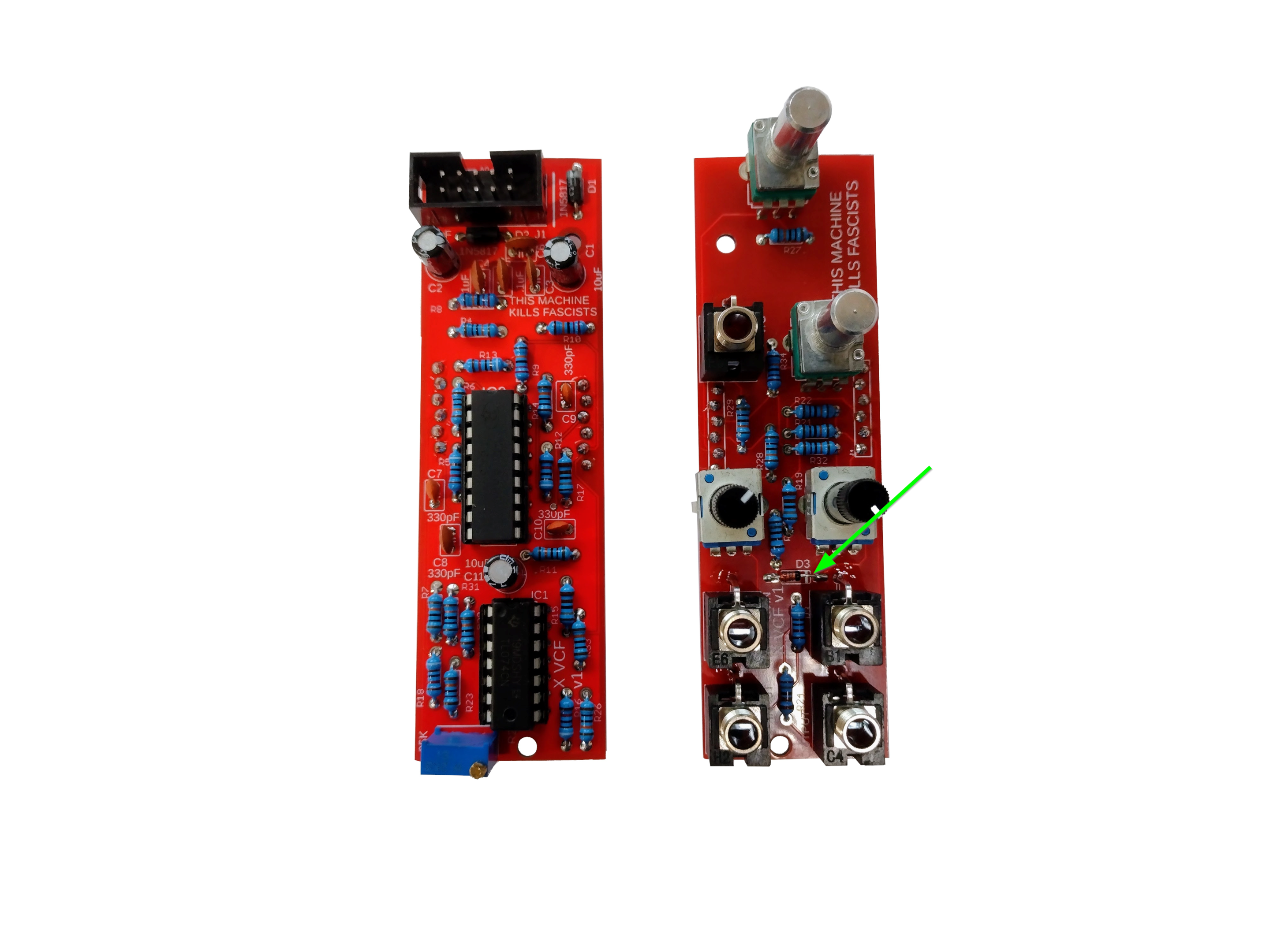
- There is one 1n4148 Diode. Mind the polarity.

- There are 18 pin and 14 pin sockets. Although the sockets have no inherent orientation, it's good to align the divots with the silkscreen to ensure you don't mess up the polarity of the ICs, which much be inserted the right way.

- The power header is shrouded and must be soldered the right way for the polarized ribbon cable.

- There are three 10uF Capacitors. They are polarized.
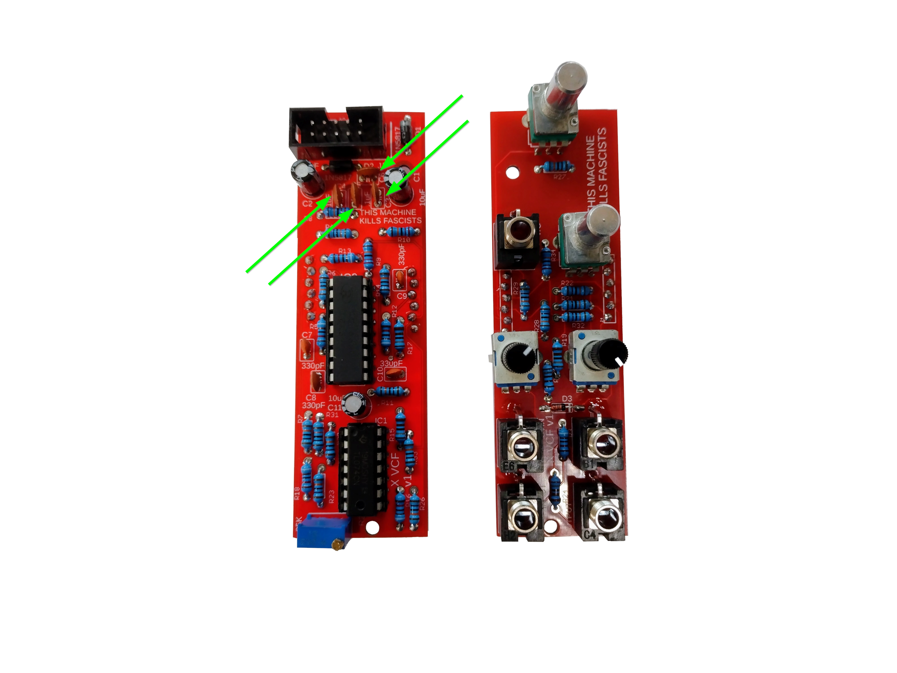
- There are four .1uF capacitors.
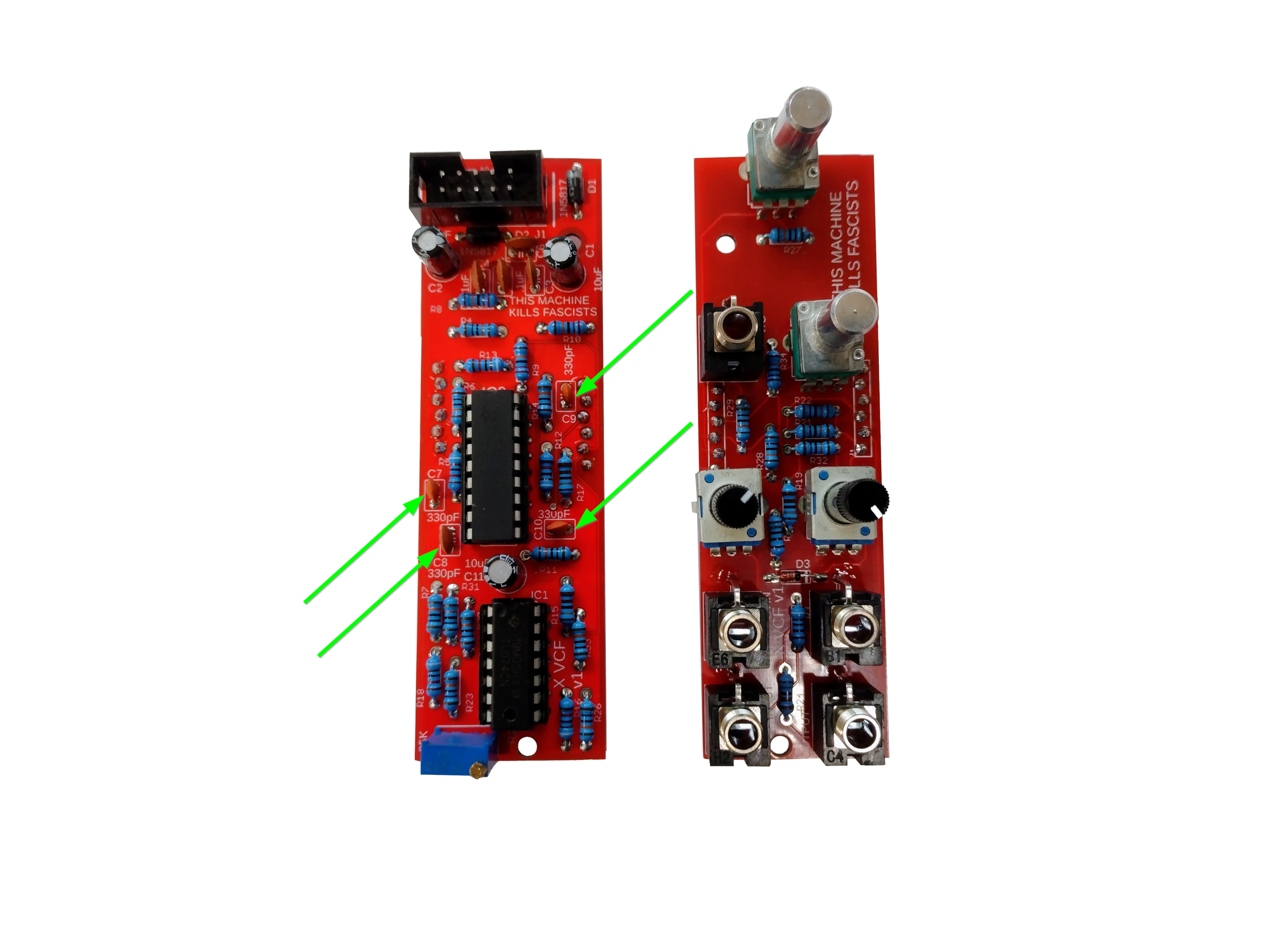
- Add the four 330pF capacitors.
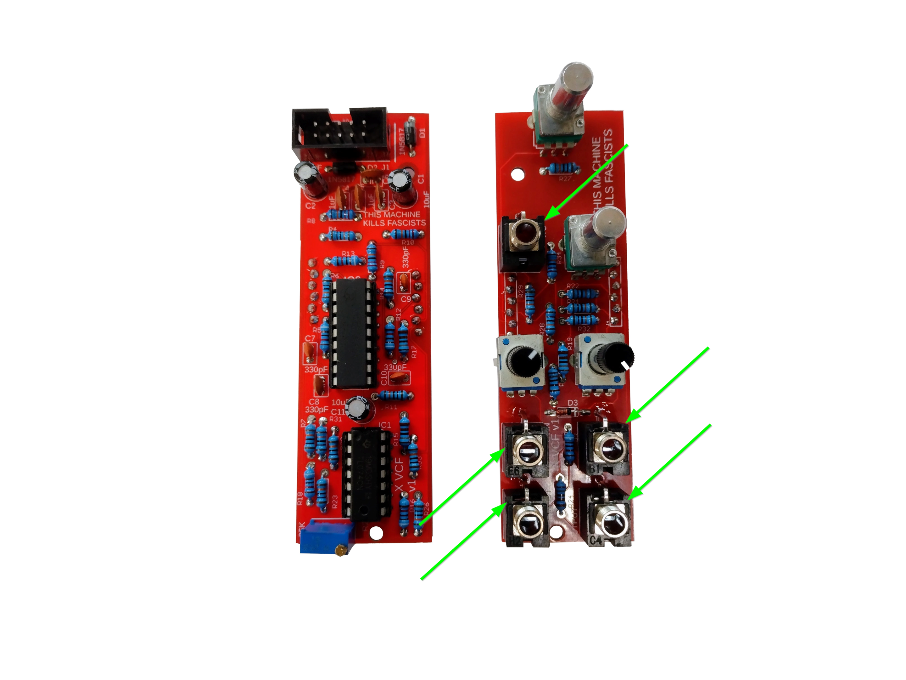
- At this point solder the five jacks. I like to place them in and solder the ground lug (the lug that sticks out) from the top and then solder the other lugs from the bottom of the PCB.
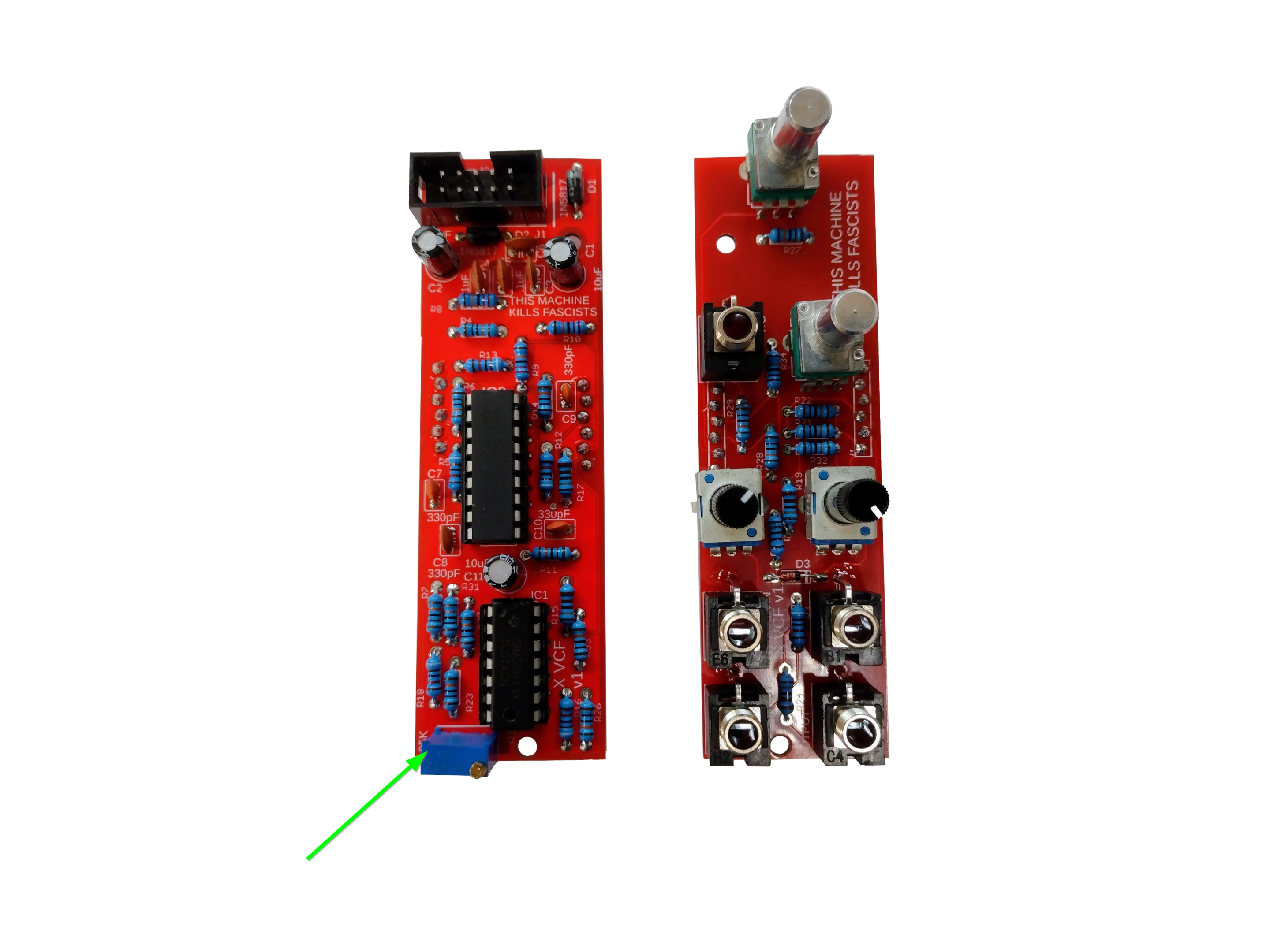
- Now we'll add the 25K Trimmer.
- Next we'll add the two B10K Alpha pots. You may want to place the panel over the pots and jacks to ensure they are straight.

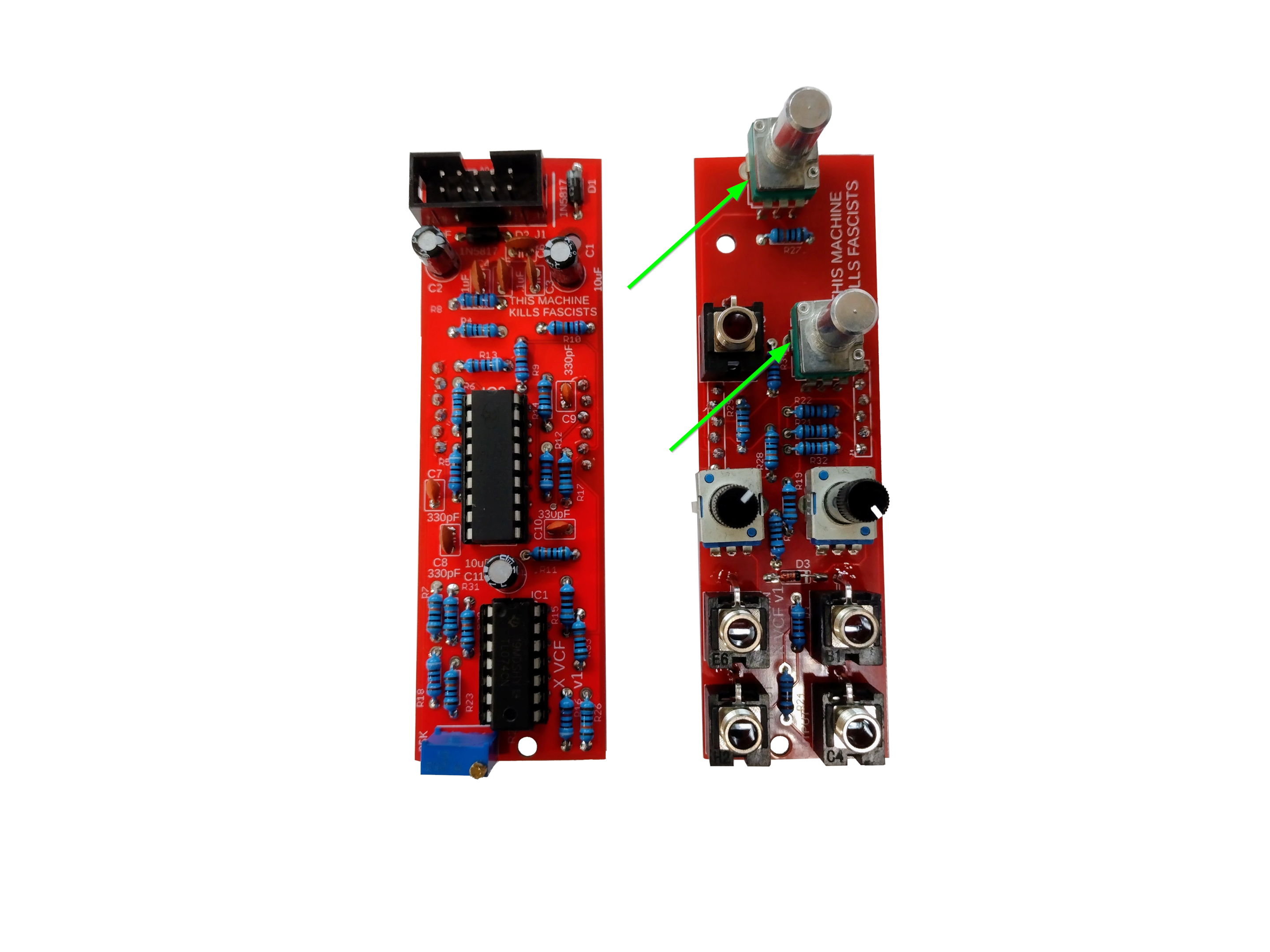
- Next add the two B10K tall trimmers, again aligning them with the panel.
- Now fit the two boards together. You are ready to test!
- Let’s test the module. Without applying power, ensure that there is no continuity between the positive, ground, and negative voltage power pins using a digital multi-meter. You test by connecting one test lead of the multimeter to ground and the other to positive voltage. There should be no continuity.
Next test by connecting one test lead of the multimeter to ground and the other to negative voltage. There should be no continuity. Assuming there is no continuity there, you are good to apply power. This is why it is nice to have a bench power supply to test a module apart from your Eurorack system. If everything looks good, you are good to test prior to applying the panel and finishing up. - On the rear is a volt per octave trimmer. To calibrate (if you care to) put res up to max, no input, plug into a very good tuner, and put a v/octave signal into the jack next to the res pot. Play an octave C to C (or whatever notes separated by an octave) and adjust the trimmer until you get close to an octave. If you don't want to use it as a VCO, you don't need to adjust it.
- Share your build on Facebook and Instagram!
- If you are having any issues at all, please contact me at: https://aisynthesis.com/contact/.