
How to Build the AI004 V2 DIY Eurorack OTA Filter
This is the build guide for the AI004 V2 OTA Filter DIY Kit
Versions
This is a build guide for the V2 version of the PCB. The V1 version is here. The V2 is theoretically the same as the V1 version, and simply incorporates the kludges that are advised for the V1 version. The V1 actually works without any kludges, but post release, changes were discovered that I suggested be made. The sound is, or should be, exactly the same.
The V2 Version of the PCB has "V2.5" printed on it, and no rectangular hole on the front PCB. The V1 does have a rectangular hole on it.
Table of Contents
- Resources
- About the DIY Eurorack OTA Filter Kit
- Tools Needed
- BOM (Bill of Materials)
- Build Guide
- Testing and Calibration
1. Resources
2. About the DIY Eurorack OTA Filter Kit
If you are new to DIY electronics, this is the third or fourth module you should build. The first module, the AI001 Multiple Eurorack Synthesizer Module is ideal for beginners, as it teaches how to solder, and familiarizes the builder with the concepts of signal and ground. The second module, the AI002 DIY Synthesizer Mixer module familiarizes you with pots, ICs, and Eurorack power. If you successfully built those, this DIY Eurorack OTA Filter is the perfect bridge between beginner and medium to difficult modules. It has two ICs, and a fair number of steps, but can still be built in a single sitting. The DIY Eurorack OTA FIlter Kit is an Filter based upon the classic MS20 design with the ability to filter in both hi-pass and lo-pass modes. The difference between the V1 and V2 version is that the V2 incorporates the kludge in V1, and omits two unnecessary parts.
3. Tools Needed
- Soldering Iron: Cheap
or Nice
- Solder
- Soldering Tip Cleaner
- Diagonal Cutters
- Micro Shears
- Precision Screwdriver Set
4. BOM
| Category | Part | Quantity | Designation |
|---|---|---|---|
| Capacitor (Electrolytic) | 10uF | 3 | C1-2; C9 |
| Capacitor | .1uF | 4 | C3-C6 |
| Capacitor | 4700pF or 4.7nF | 1 | C10 |
| Capacitor | 1nF | 2 | C7-8 |
| Hardware | Female 6 Pin Header | 2 | J3 |
| Hardware | Male 6 Pin Header | 2 | J4 |
| Hardware | Power Header | 1 | Power |
| Hardware | 14-Pin IC Socket | 1 | IC2 |
| Hardware | 16-Pin IC Socket | 1 | IC1 |
| Hardware | Jack | 4 | |
| LED | Red LED | 2 | D3,D4 |
| IC | TL074 | 1 | IC2 |
| IC | LM13700 | 1 | IC1 |
| Potentiometer | 9mm Alpha Potentiometer B100K | 1 | CV1 Trim |
| Potentiometer | 9mm Alpha Potentiometer A100K | 2 | Resonance, InVol |
| Potentiometer | 9mm Alpha Potentiometer B50K or B10K | 1 | Frequency |
| Resistor | 10R OR 1n5817 Diode | 2 | R1-R2 |
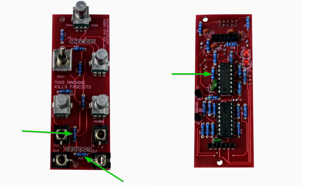
| Resistor | 10K | 7 | R6, R7, R10 - R13, R16 |
| Resistor | 1K | 1 | R25 |
| Resistor | 220R | 4 | R3, R5, R8, R9 |
| Resistor | 4.7K | 2 | R17, R27 |
| Resistor | 68K | 1 | R19 |
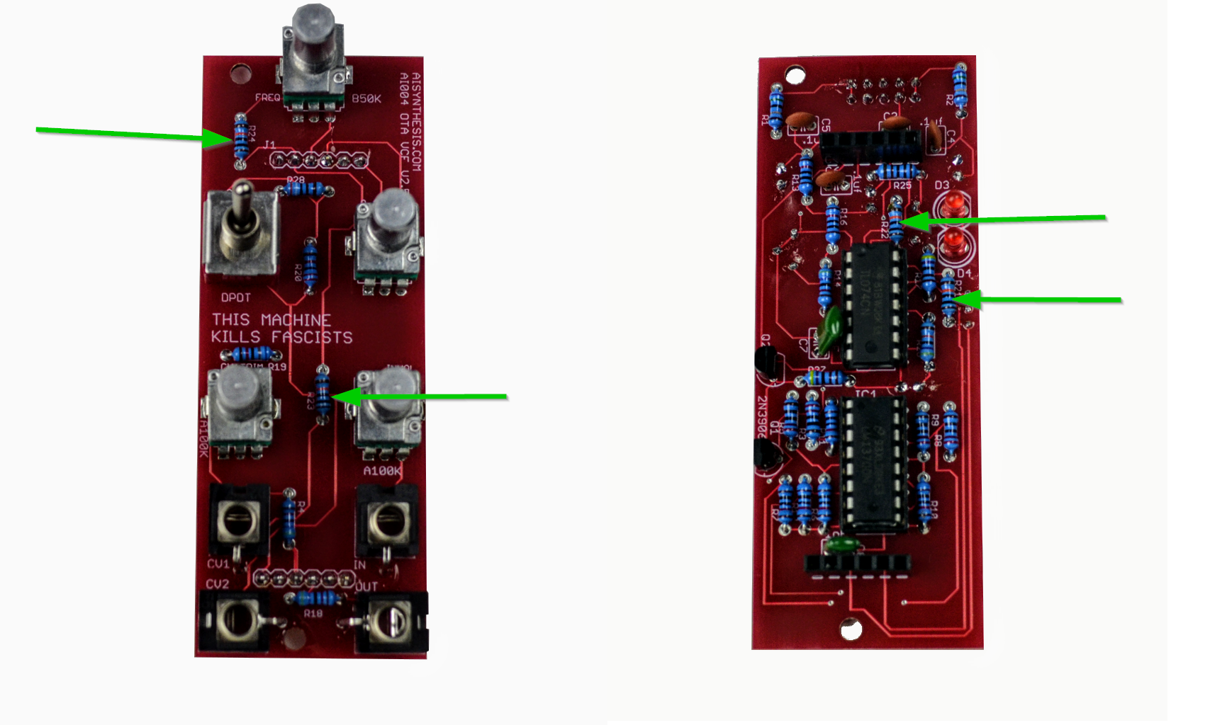
| Resistor | 100K | 4 | R21-24 |
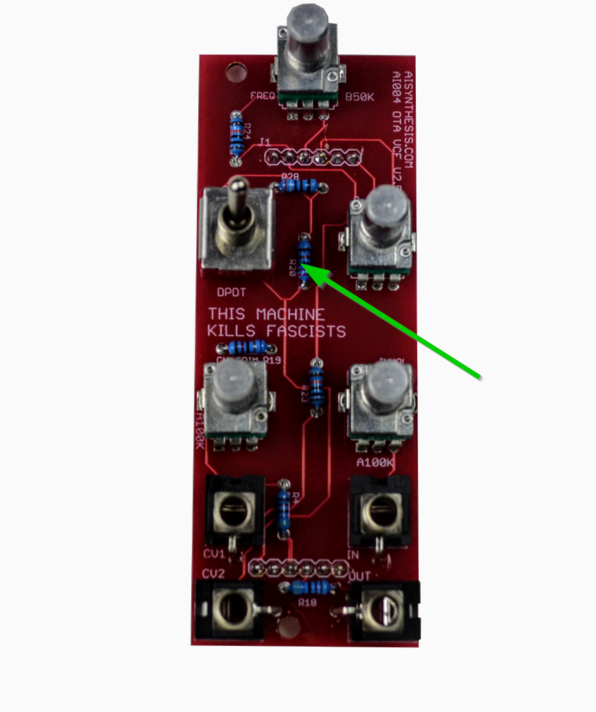
| Resistor | 22K | 1 | R20 |
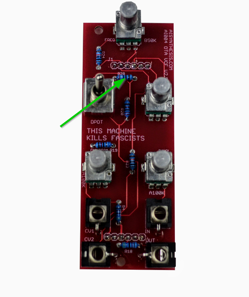
| Resistor | 3.9K | 1 | R28 |
| Resistor | 470K | 1 | R26 |
| Resistor | 47K | 3 | R4, R14, R18 |
| Spacer | 3x8mm PCB Spacers | 2 | n/a |
| Switch | DPDT Switch and optional cap | 1 | SW1 |
| Transistor | 2N3906 | 2 | Q1, Q2 |
| Trimmer | 1K | 1 | F-Tune |
| Trimmer | 100K | 1 | A-Trim |
| Trimmer | 50K | 1 | ResDrive |
| Power Cable | Eurorack Power Cable | 1 | n/a |
5. Build Guide
-
-
- First, gather your parts together, and snap the two PCBs in half in order to make two PCBs.
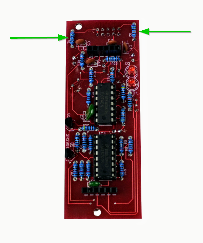
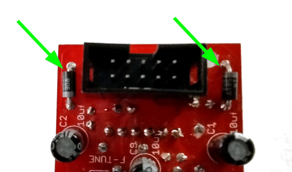
- First, gather your parts together, and start with the two 10R resistors OR 1N5817 Diodes at R1 and R2. Your kit may have either part, and both are fine. The kits are transitioning to using 1N5817 Diodes instead of 10 Ohm resistors for further reverse power protection. The 10 Ohm resistors are not polarized and have no orientation. The 1n5817 Diodes must be put in the correct orientation, shown below. When I re-order PCBs they will have the orientation on the PCB. I didn't want to throw out a bunch of otherwise good PCBs.
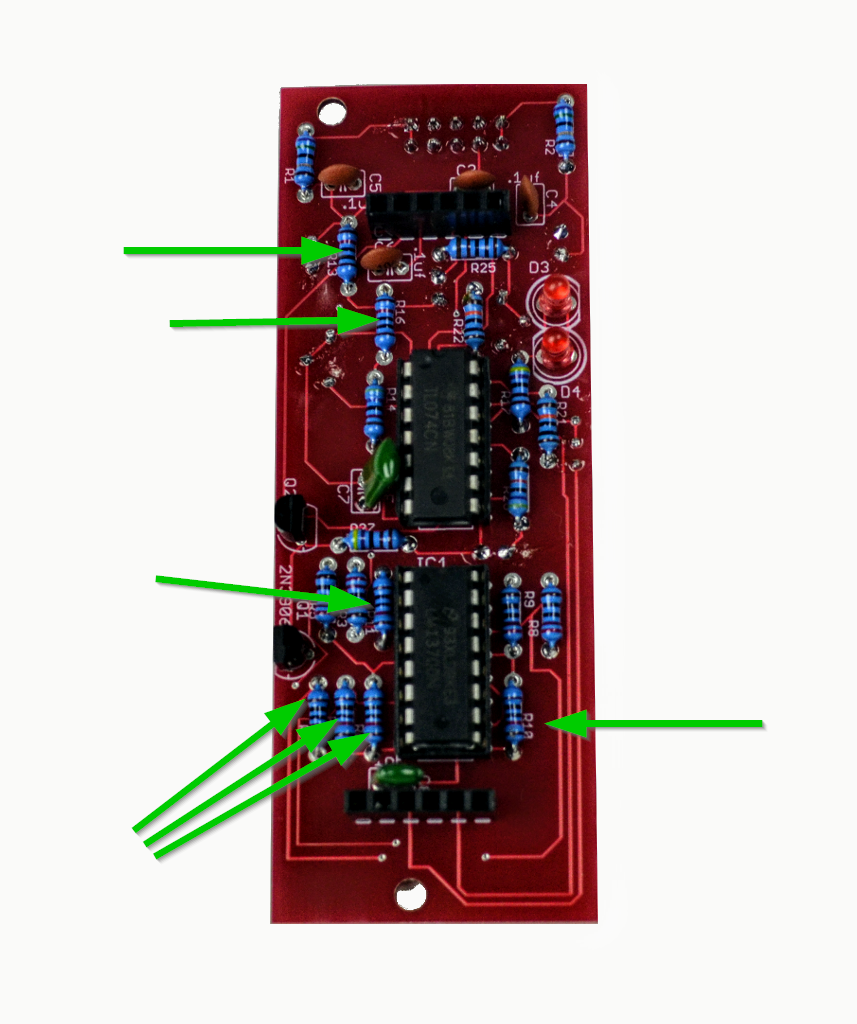
- After that move on to the 7 10K resistors on the bottom board.
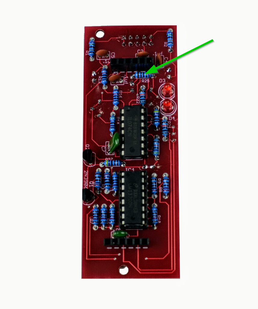
- There is one 1K resistor at R25 on the bottom board.
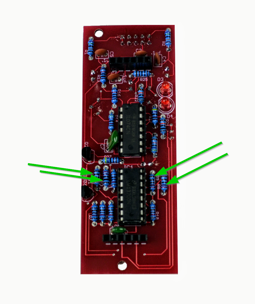
- There are four 220R resistors on the bottom board, two on either side of the LM13700.
- There are two 4.7K resistors on the bottom board at R17 and 27.
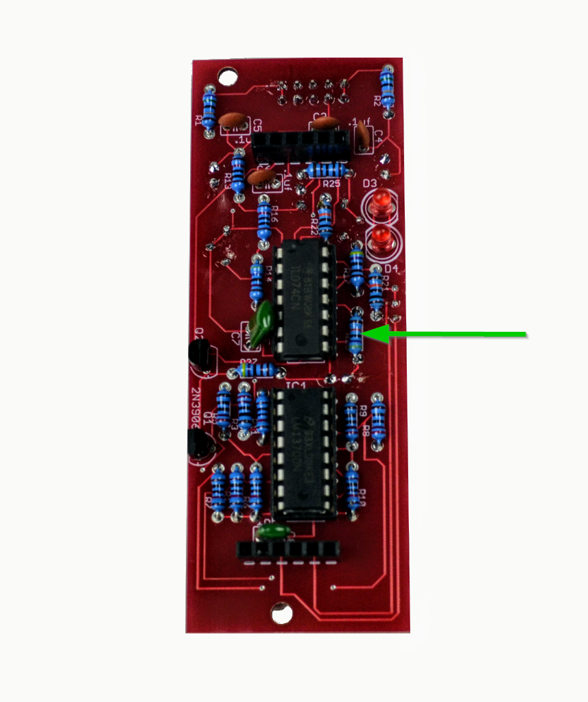
- There is one 470K resistor at R26.
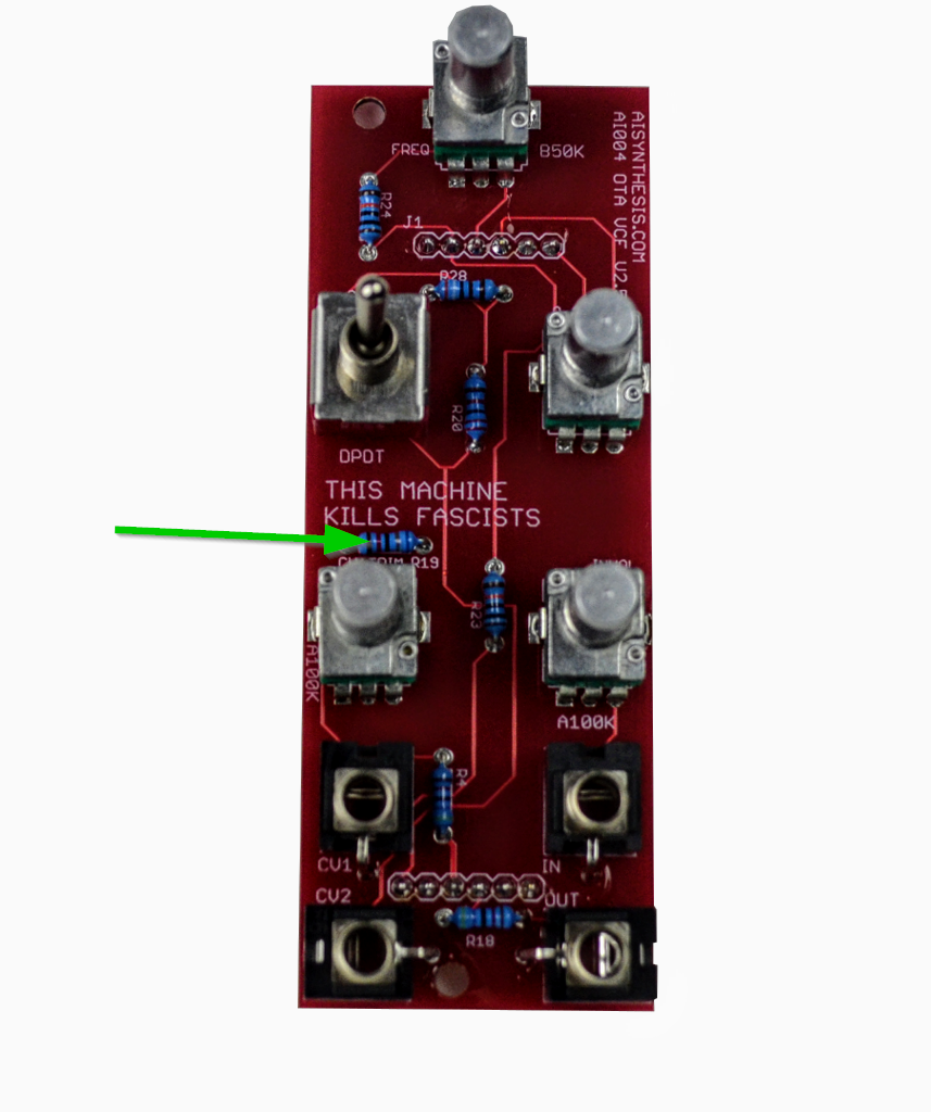
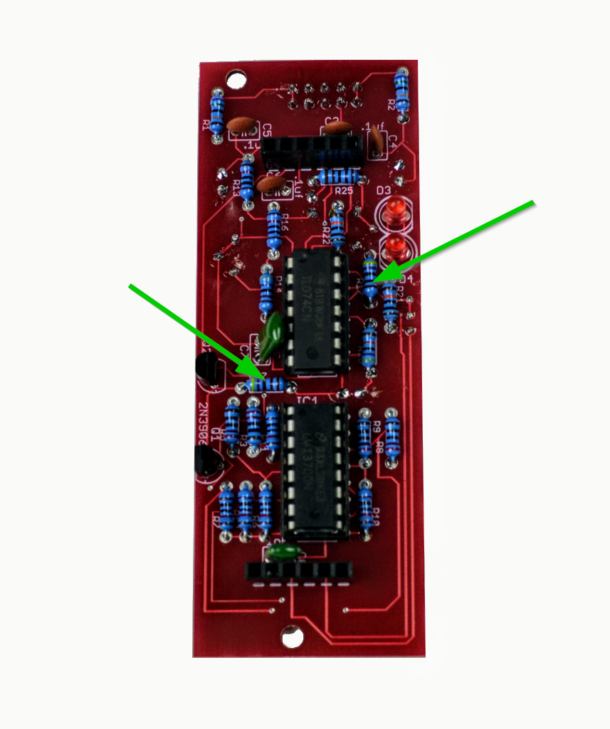
- There is one 68K resistor on the top board at R19.
- There is one 47K resistor on the bottom board, and two on the top board.
- There are four 100K resistors. Two on the top board, and two on the bottom.
- There is one 3.9K resistor on the top board.
- There is one 22K resistor on the top board.
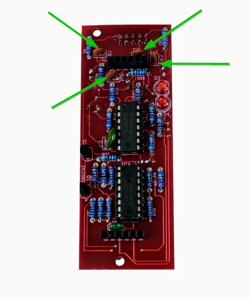
- There are four .1uF capacitors, on the bottom board, all for power protection.
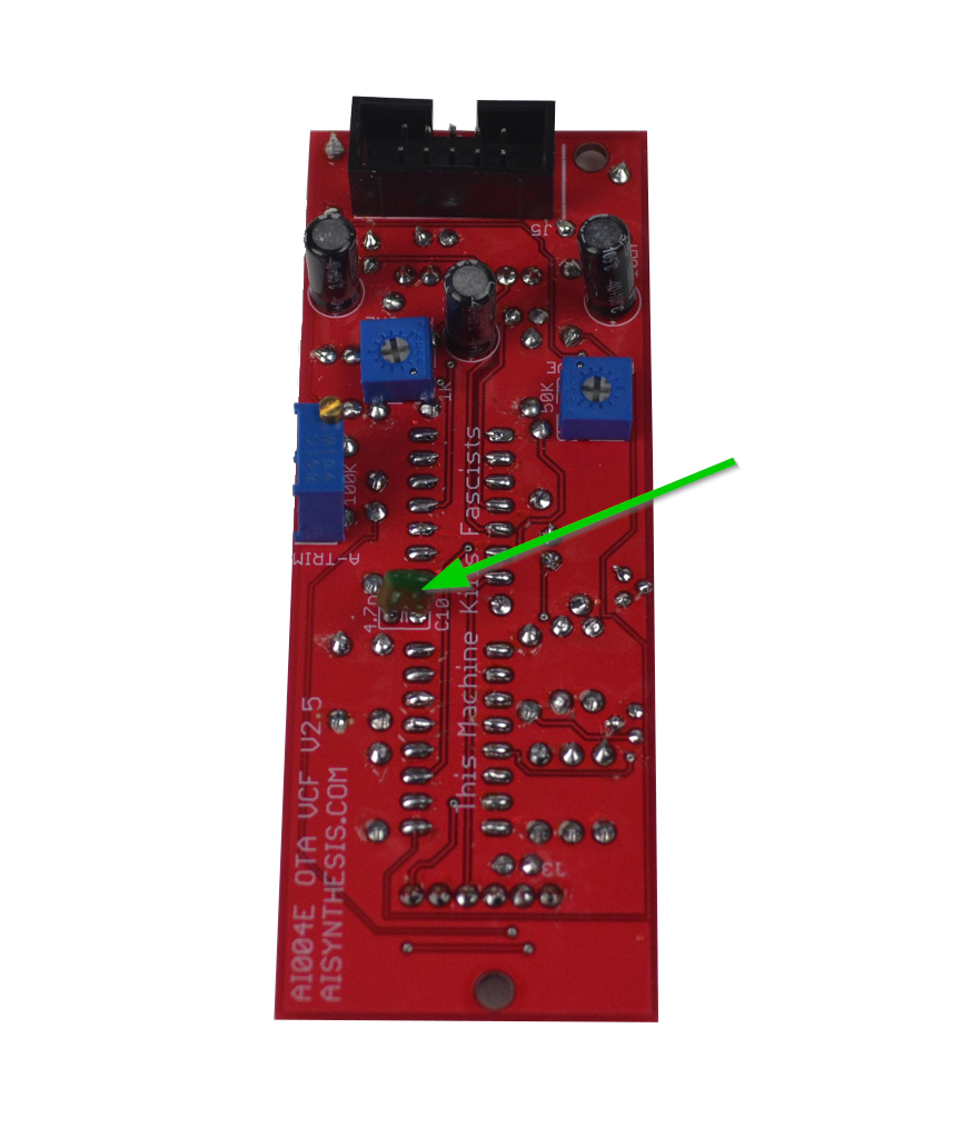
- There are components on both sides of the bottom board, so the order can be a bit tricky. We're going to do the single 4.7nF (your cap might be labeled 4700pF or .0047uF - it's all the same) on the rear of the bottom board before we do the IC sockets. You can do it after the IC sockets, but I think it is easier to solder it in without the sockets in place.
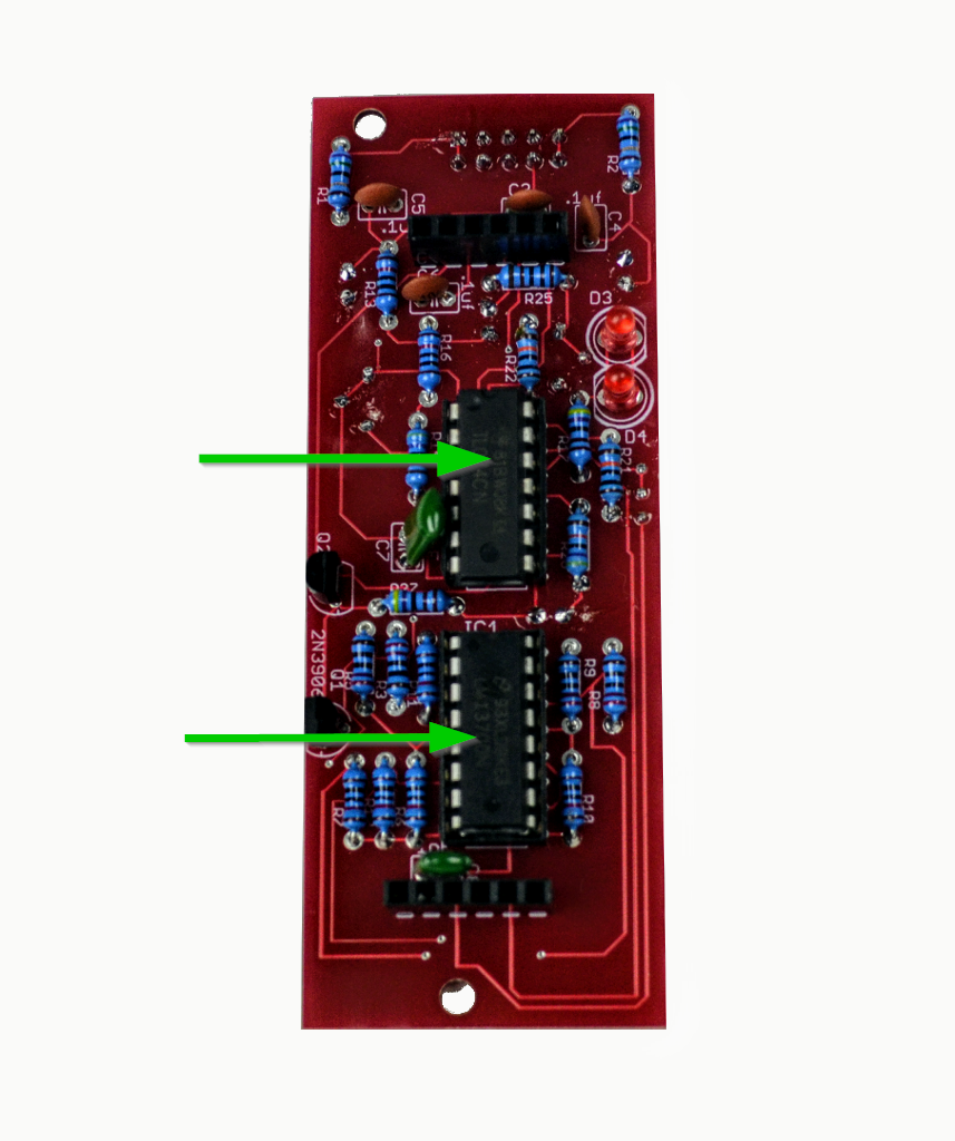
- Now we'll do the IC sockets, and then move on to the other side of the bottom board. Be sure that the sockets orientation matches the silk screen, as that will help you insert the ICs the right way. If you insert them the wrong way, you will short the power and ruin some things.
- On the reverse side, we can do the power header. You may need to "tack" the header on with a bit of solder to start. Be careful with the amount of heat you apply, as the black plastic can be melted. The "notch" is on the top side of the board. That will ensure that the power cable's red stripe is on the right (when viewed from the rear) and that the power cable is orientated correctly.
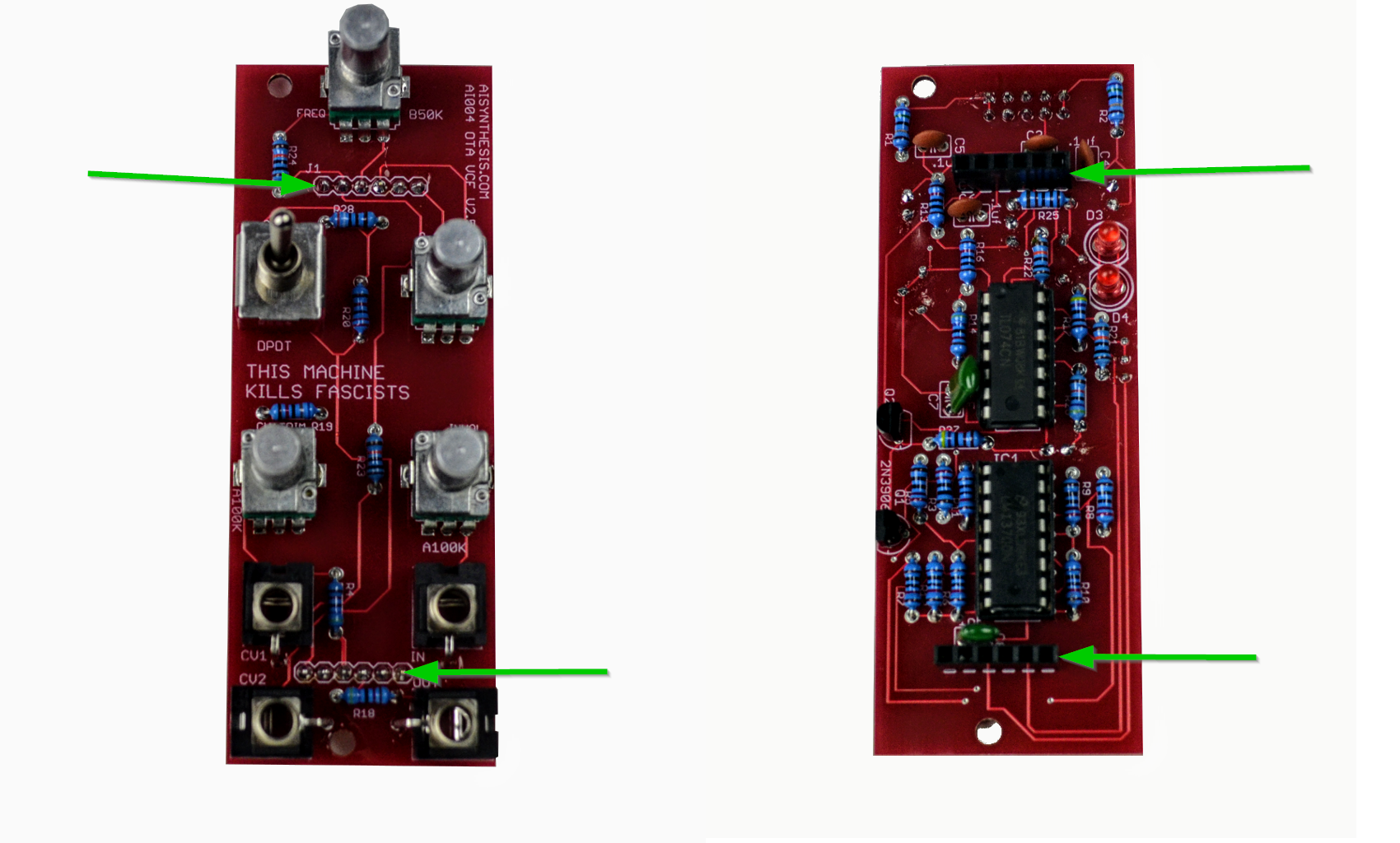
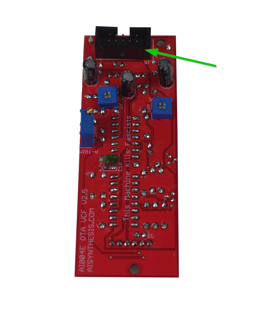
- At this point it is good to add the headers J1-J4, as other components will soon get in the way. These headers will connect the two boards and transmit signals between the two. It doesn't matter which side is the "male" or "female" half, so long as one goes into the other. I find that the easiest method is to put the headers together and put the boards together, and then solder the headers in with the boards put together. Otherwise they often end up a bit skewed. I like to start with the panel-side PCB facing down and start from there. Be sure to solder them to the sides shown above, so that the "panel-facing" side of the PCB and the "power end" of the PCB end up on the right sides. When you are done, be sure to visually check for bridges between the pins pf the headers, a common error.
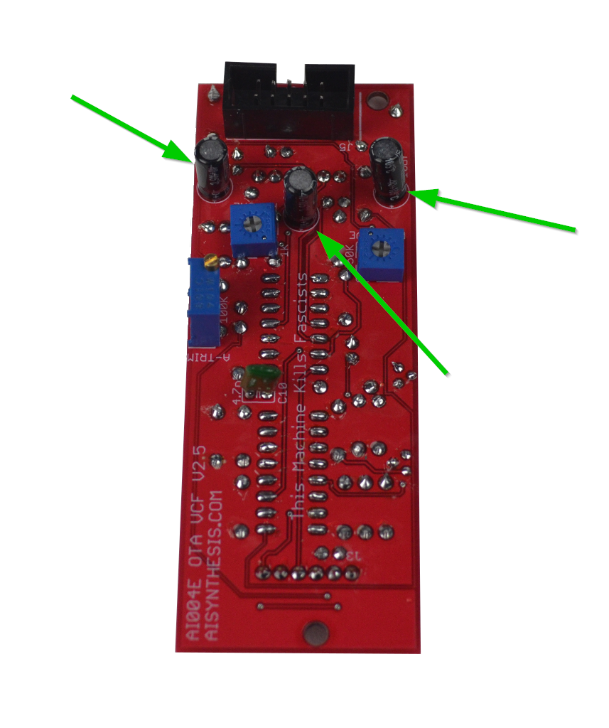
- Now we'll add the three 10uF polarized capacitors. Be sure that the orientation is correct and that the "negative" stripe is not facing the silkscreened "+."
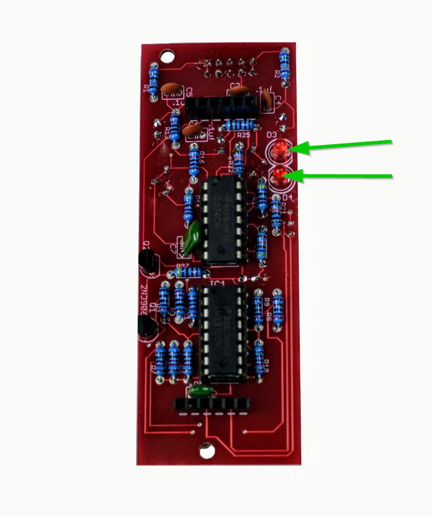
- Now the two LEDs. Be sure the orientation is correct. The longer lead is the anode, and that should align with the rounded side of the silkscreen. the opposite, shorter lead is the cathode, which should align with the flat side of the silkscreen. The LED itself also has a slight flat side on the side with the shorter leg, but it can be hard to see. It is good to do so before the trimmers as they'll get in the way.
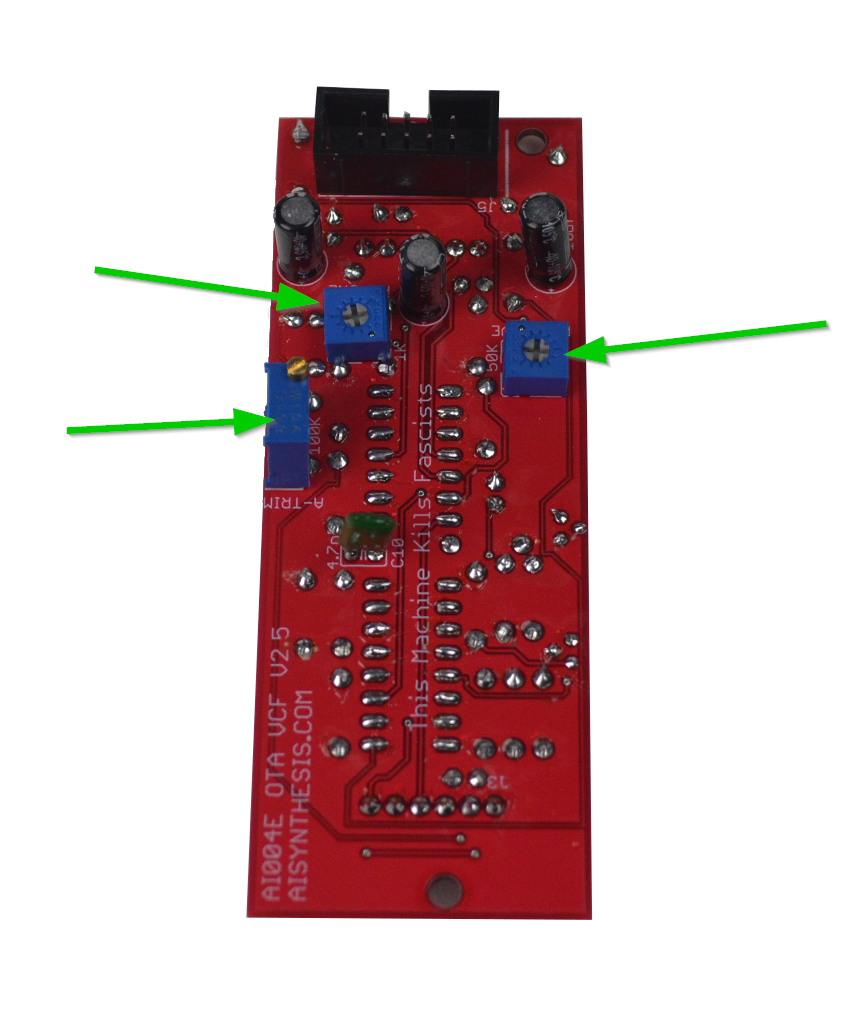
- Next we'll add the three trimmers on the rear - don't get them mixed up.
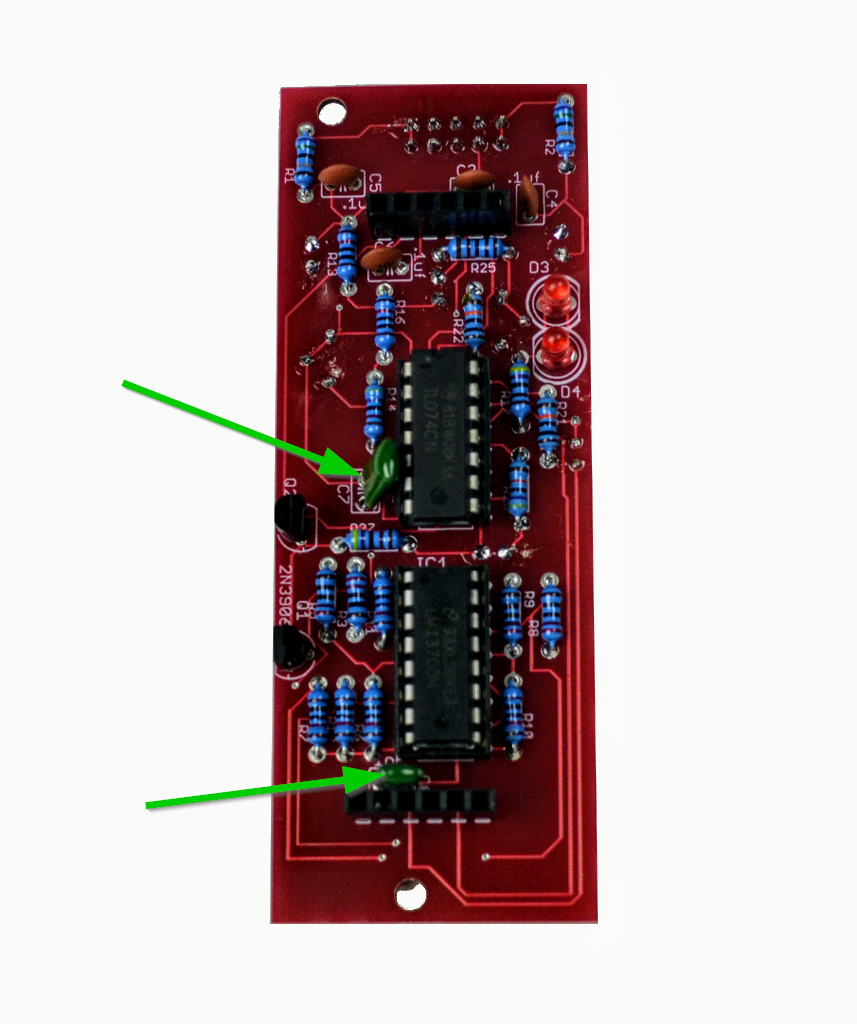
- Now we'll solder the two 1nF capacitors at C7 and C8. Ceramic caps and the ones in the kit should fit per the PCB, they'll just be close to the other PCB. You can seat them prior to soldering, as shown below. They aren't polarized, so you can put them on the rear side of board if they sit too tall on the PCB. Your caps may read 1000pF or .001uF, which are the same value as 1nF (see the capacitor conversion page).
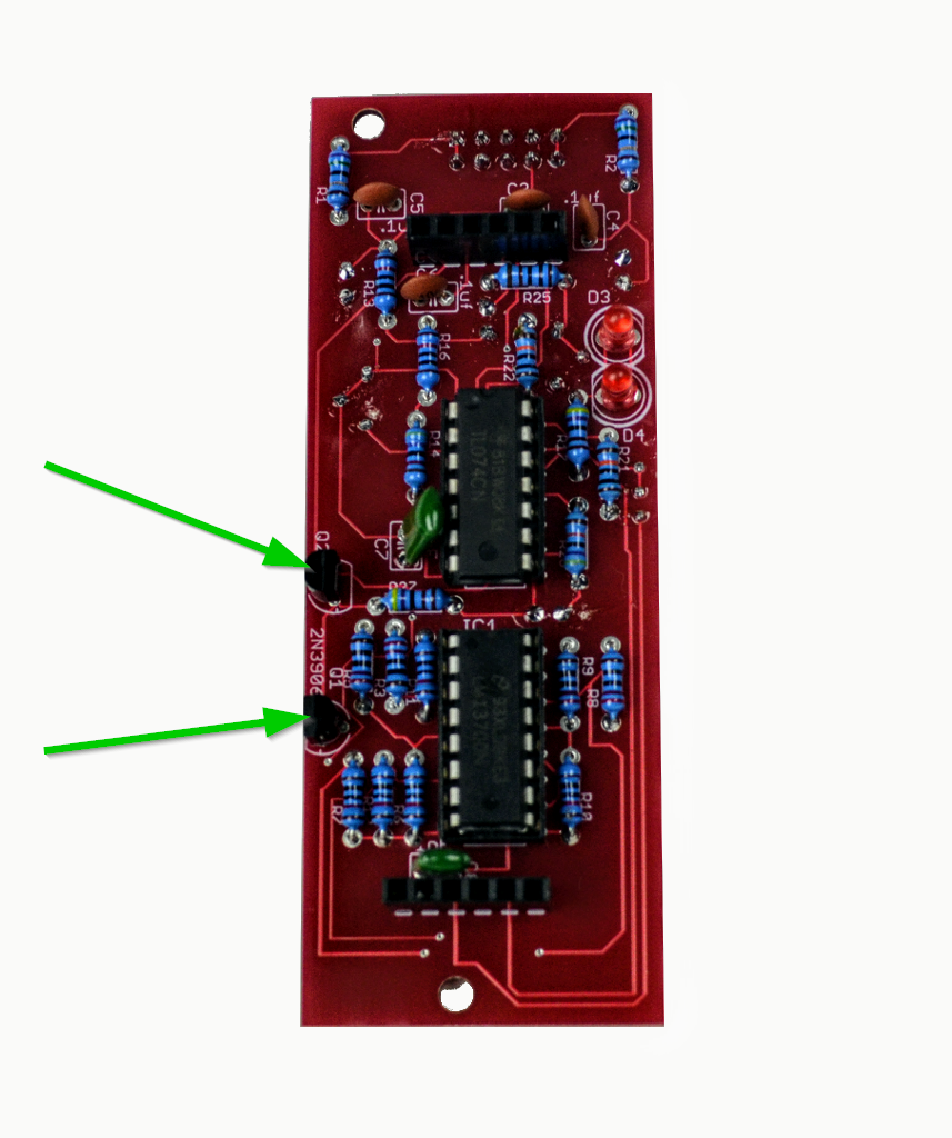
- Now we'll do the two 2n3906 Transistors at Q1 and Q2. Be sure that the transistors match the silkscreen orientation.
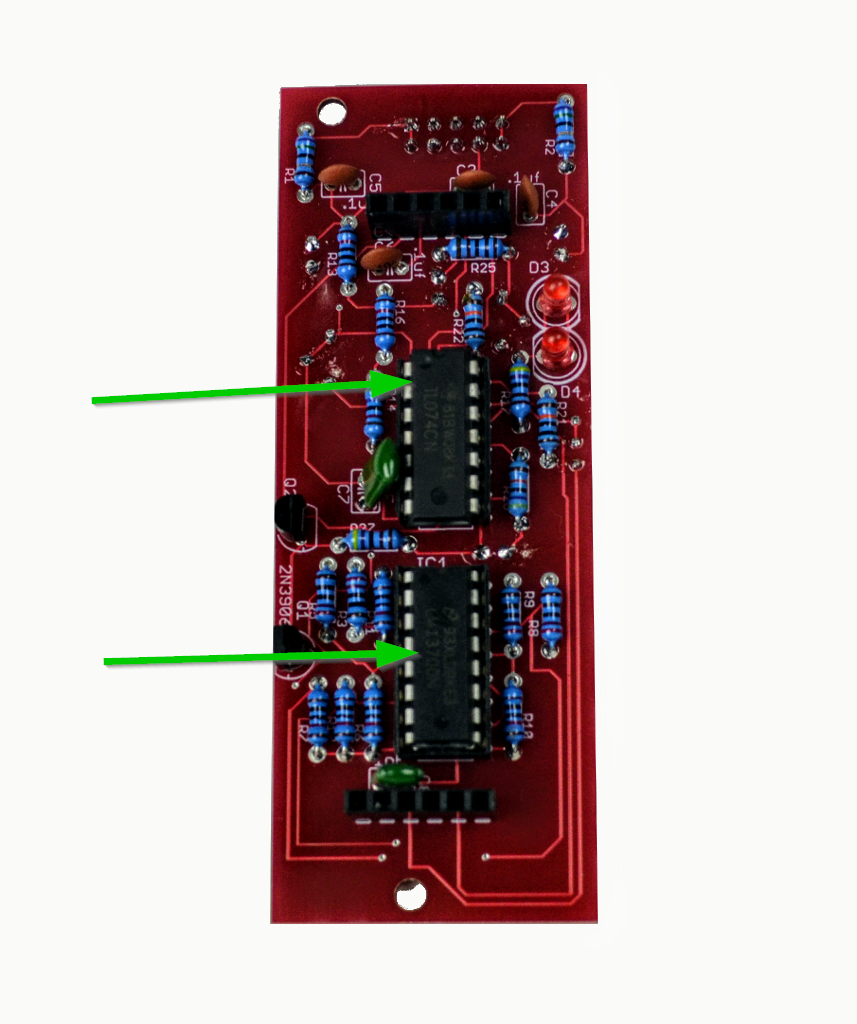
- When you're done, you can insert the ICs, as we're done with the bottom board. Ensure that the ICs are fully seated. If the LM13700 is not fully seated in the socket, the module will work, but you may experience sluggish changes to the filter frequency.
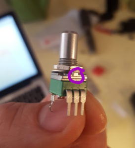
- Time for the pots. Before soldering any of the potentiometers, undo the nut and washer, and use Diagonal Cutters to remove the nubs if your pots have them. You can use micro shears, but you might break them.
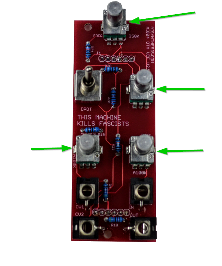
- On the top board is one B50k (might read B503) or B10K (might read B103) pot for the Frequency pot, and two A100k (might read A104) pots for the "Resistance" and "Audio In," the CV1 pot is marked A100, but a B100K (B104) will ensure that the attenuverter can be at 0 at 12'o-clock, otherwise the o point will be around 2 or 3 o-clock. You may want to use the panel to align the pots before soldering them to the PCB.
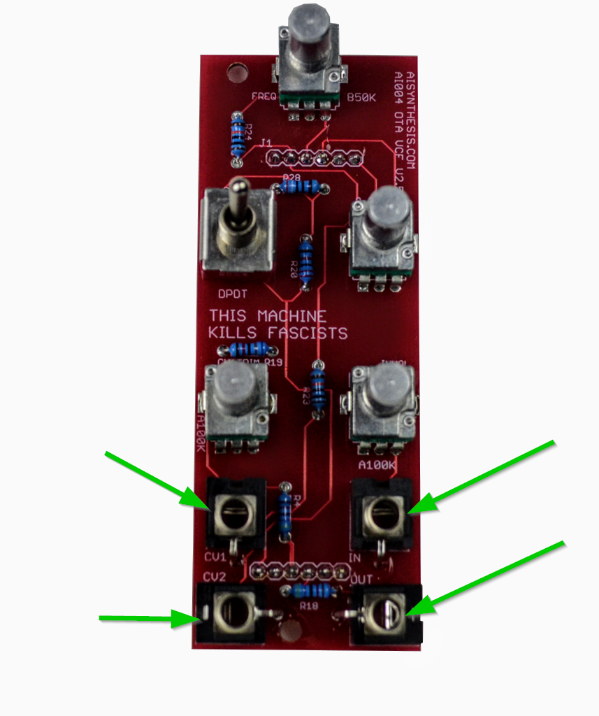
- Then solder in the jacks. I like to fit them and solder the ground lug on the panel-facing side of the PCB, and then get the other lugs on the other side. This helps the jacks fit snugly against the PCB.
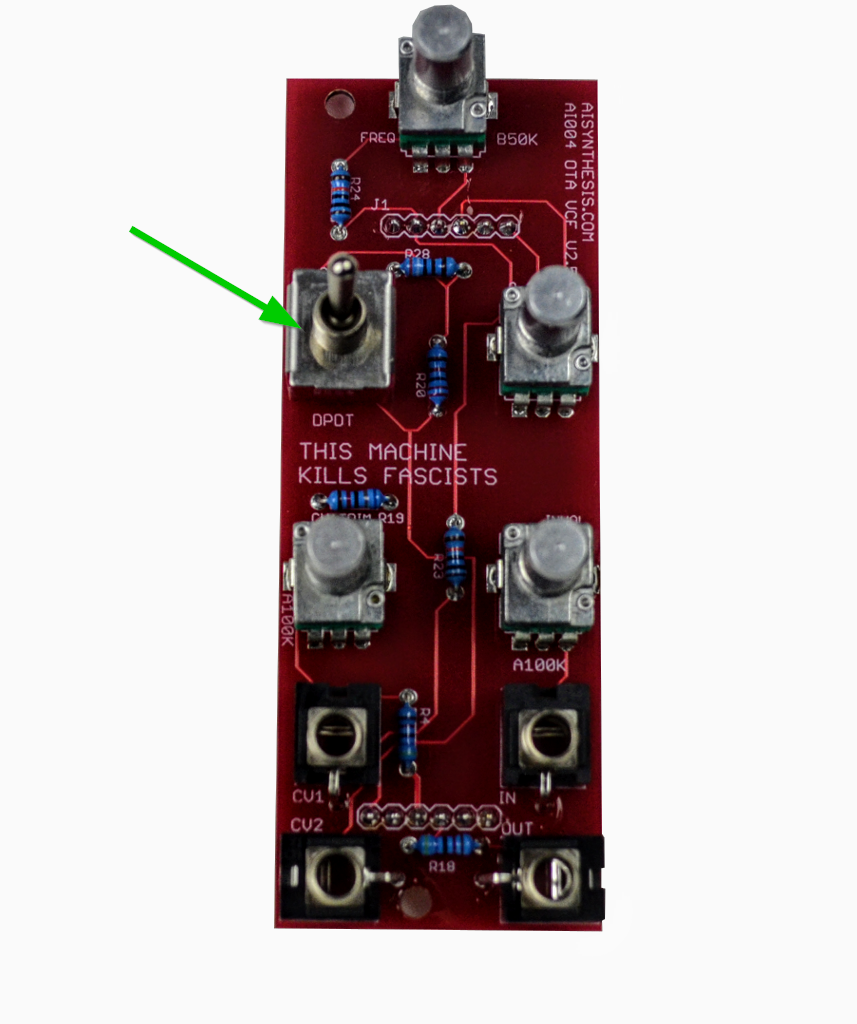
- To install and solder the DPDT switch. Install the PCB mounting hardware on the panel PCB. Now seat the DPDT switch and place the panel on. You can gently place the nits on to hold the panel in place, and then solder.
- Now fit the two boards together. You are ready to test!
- First, gather your parts together, and snap the two PCBs in half in order to make two PCBs.
-
Testing and Calibration
- Before you finally peel of the panels protective layer and put on the panel, let’s test the module. Without applying power, ensure that there is no continuity between the positive, ground, and negative voltage power pins using a digital multi-meter. You test by connecting one test lead of the multimeter to ground and the other to positive voltage. There should be no continuity.
Next test by connecting one test lead of the multimeter to ground and the other to negative voltage. There should be no continuity.
Next test by connecting one test lead of the multimeter to positive and the other to negative voltage. There should be no continuity. Assuming there is no continuity there, you are good to apply power. Eurorack, tragically, has no universal power connector format. This has resulted in far too many blown up modules. AI Synthesis modules follow the most common format, in which there is a white stripe next to the negative end of the power connector, and this is typically where the red stripe of the power cable should be aligned, but check your power supply for details. - Connect the two PCBs and power on the module. I like to give a freshly powered module a few seconds to ensure that nothing smokes and there is no danger of fire. This is why it is nice to have a bench power supply to test a module apart from your Eurorack system. If there is no smoke, proceed to an audio test.
- Audio Test: If the module works on power up, proceed to an audio test. Plug an oscillator or other sound source (mp3 player will work) into the In jack, turn the volume up, and use headphones to monitor the output. You should hear the signal through filter, though it may be a bit quiet, as there is significant gain transfer to the resonance in the circuit, and the passed frequencies are quiet, (which is why I recommend using a VCA with the module). If so, you are ready to screw the boards together with the PCB hardware and then calibrate. If not, check your soldering, and/or email me with high res images of both sides of each board.
- Attenuverter Calibration. I like to mark the positions of the pots with a sharpie, so I don't have to put on the knobs until I know everything is good to go. With a sound source plugged in (an oscillator works best) plug in a control voltage source, such as a square wave LFO, or the looping output of the AI003 Looping envelope generator at a fast speed. Set the CV in pot to point at 12'o clock, and, using a micro screwdriver, adjust the A-Trim Trimpot until you do not hear filter modulation.
- Filter Tuning. There is no scientific setting for this (that I have discovered yet). The F-tune trimmer can be thought of as a "fine adjust" for the Frequency pot on the front panel. I adjust this my plugging it into my system, and running lots of audio through it, tuning this to taste to that I get the best balance of filter sweep range in both LP and HP modes. In the MS-20, there are separate LP and HP filters, so you may have a hard time getting the perfect sweep for both modes (you could also use a fixed voltage mixed in to the cv input to acheive offset).
- Resonance Trimming - The Resdrive trimmer should be set to taste. More drive will increase the ammount of gain to the resonanced frequency, at the cost of gain to the "passed" frequencies.
- Share your build on Facebook and Instagram!
- If you are having any issues at all, please contact me at: https://aisynthesis.com/contact/.
Oscillator Outputs Matter
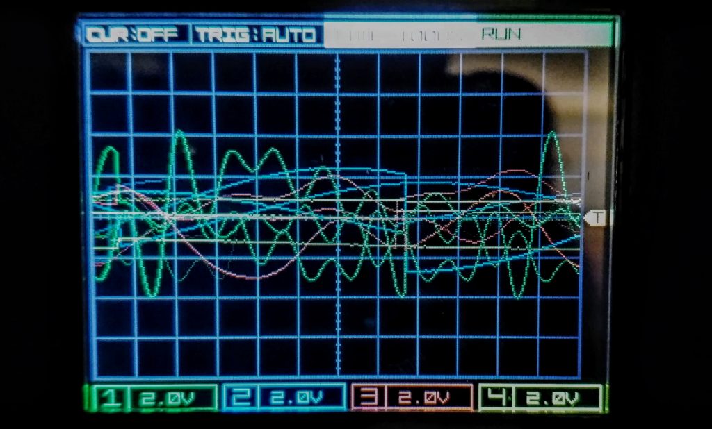
The AI004 was/is designed to be used with an oscillator with a 10v peak to peak waveform. That is the "standard" in other formats for an oscillator.
In Eurorack there are no standards for this. Here is a scope showing 4 different oscillators in my rack. The green signal is 8v peak to peak, the blue is about 5, the yellow is a measley 4v, and the red looks like 5 or 6. These oscillators CAN be used with the AI--4, but your oscillator output will absolutely, 100% affect the tone of the filter, especially one like this in which the resonance is keyed onto the input signal.
A VCA is your friend
As with most OTA filters, (as well as diode ladder, cascade, CEM, and SSM designs,) wherein resonance is achieved via negative feedback, the non-resonanced signal (the passed signal) will drop. When used in conjunction with a VCA, this is trivial.
There are ways to compensate for this by injecting some of the original signal into the feedback loop, or adding extra gain circuitry, but this has its own issues, and was avoided in this design, in large part for authenticity. In the "normal" mode, there is a normal volume drop, and in the "extended resonance mode" you will see a greater volume drop to the "passed signal." Due to the high resonance gain, there is a large drop, again, if using a VCA, this is trivial.