
How to Build the AI006 Eurorack Stomp Box Adapter Module
This is the build guide for the AI006 Eurorack Stomp Box Adapter
Table of Contents
- Resources
- About the AI006 Eurorack Stomp Box Adapter Module
- Tools Needed
- BOM (Bill of Materials)
- Build Guide
- Testing and Calibration
1. Resources
2. About the Eurorack Stomp Box Adapter Module
If you are new to DIY electronics, this is the second or third module you should build. The first module, the AI001 Multiple Eurorack Synthesizer Module is ideal for beginners, as it teaches how to solder, and familiarizes the builder with the concepts of signal and ground. This DIY Eurorack Stomp Box Adapter Module is the perfect bridge between beginner and medium to difficult modules. It has one IC, and a fair number of steps, but can still be built in a single sitting. The DIY Eurorack Stomp Box Adapter Module matches the impedance that your guitar pedals are built for, allowing you to use them to their fullest range.
3. Tools Needed
- Soldering Iron: Cheap
or Nice
- Solder
- Soldering Tip Cleaner
- Wire Strippers
4. BOM
| Category | Part | Quantity | Designation |
|---|---|---|---|
| Capacitor (Electrolytic) | 10uF | 4 | C1-2; C7, C10 |
| Capacitor | .1uF | 4 | C3-C6 |
| Capacitor | 47pF | 1 | C9 |
| Capacitor | 10pF | 1 | C8 |
| Hardware | Female 3 Pin Header | 1 | H1 |
| Hardware | Male 3 Pin Header | 1 | H2 |
| Hardware | Power Header | 1 | Power |
| Hardware | 8-Pin IC Socket | 1 | IC1 |
| Hardware | Jack | 4 | |
| IC | TL071 | 1 | IC1 |
| Potentiometer | A100K | 2 | Synth, Fx |
| Resistor | 10R OR 1n5817 Diode | 2 | R1, R2 |
| Resistor | 1K | 2 | R7, R4 |
| Resistor | 10K | 1 | R8 |
| Resistor | 150K | 1 | R6 |
| Resistor | 470R | 1 | R9 |
| Resistor | 1M | 1 | R5 |
| Resistor | 22K | 1 | R3 |
| Power Cable | Eurorack Power Cable | 1 | n/a |
| Non Conductive Spacer | Non conductive 10-11mm Spacer (link not tested - they change alot) | 1 | n/a |
| Tapered M3 screw | M3x6 Tapered Nylon Screw (so it can be trimmed) see build guide | 2 | n/a |
5. Build Guide
-
-
-
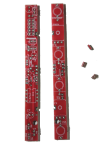
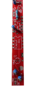
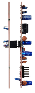
- First, gather your parts together, and snap the two PCBs in half in order to make two PCBs. Use a tool such as wire strippers or another tool to remove the PCB tabs that connected the PCBs. Since the circuit is for a 2HP panel, we don't want anything creating extra width.
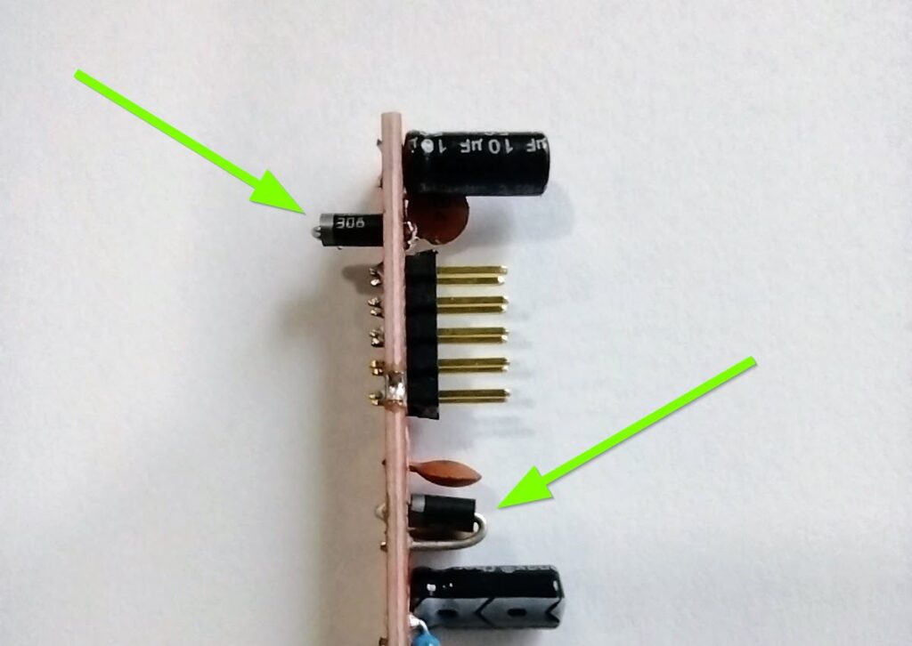
- Start by soldering the two 10R resistors OR 1N5817 Diodes at R1 and R2. Your kit may have either part, and both are fine. The kits are transitioning to using 1N5817 Diodes instead of 10 Ohm resistors for further reverse power protection. The 10 Ohm resistors are not polarized and have no orientation. The 1n5817 Diodes must be put in the correct orientation, shown below. When I re-order PCBs they will have the orientation on the PCB. I didn't want to throw out a bunch of otherwise good PCBs.
- After that move on to the single 10K resistor at R8 on the bottom board.
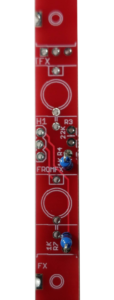
- There are two 1K resistors at R4 and 7 on the top board.
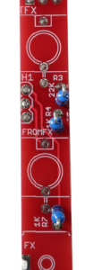
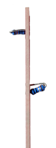
- There is a single 22K resistors on the top board as well, at R3. Note that in the photo, the metal legs of the standing resistors are oriented the same way, to help ensure that they cannot touch.
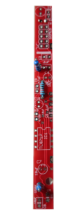
- On the bottom board, there is a single 150K resistor at R6.
- There is a 470R resistor at R9.
- There is one 1M resistor at R5.
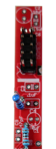
- Now is a good time to install the 2x5 pin power connector. A shrouded header will not fit in 2HP, so we'll use a 2x5 header. The white stripe on the PCB should align with the red stripe (-12V) on your power cable.
- Now move on to the four .1uF capacitors at C3-6. These are for power protection.
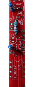
- There is one 10pF capacitor at C8 on the bottom board.
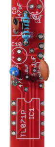
- There is one 47pF capacitor at C9.
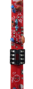
- Now we'll move onto the IC socket. ensure that the divot in the header faces up, matching the PCB, so that you remember to put in the IC the right way, and avoid shorting it.
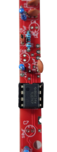
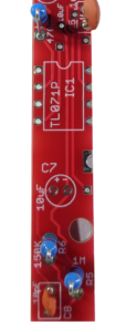
- Now we can install the TL071 IC. Ensure that the "dot" on the IC, which signifies pin 1 of the IC, is at the top left.
- Now install the four 10uF electrolytic capacitors. These are polarized, so it is important to get them right. The stripe on the cap is the negative side, which is also the side with the shorter leg, and you can use the silkscreen to align them (or open the above image in a new window to view a larger vision).
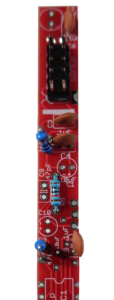
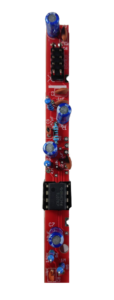
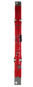
- Now install the male and female 3 pin headers. I like to place the headers in, and then put the module on its side with the headers connected, and install each side. be sure that you are installing the headers on the correct sides (opposite the resistors on the front panel and opposite the power header on the rear panel.
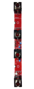
- Now we'll do the four jacks on the front panel. I like to rest the PCB on a candle holder or cup of some kind with the top facing up, place the jacks flat, and tack the ground connections first. Once I solder those, I flip the board over and solder the other pins, and re-flow the solder on the ground pins, adding more solder if necessary.
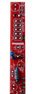
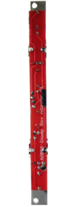
- Now it is time for the A100K trimmers on the front panel. Because this circuit is for a 2HP panel, we are using tall trimmers instead of Alpha pots. I quite like the way these pots can fit into different designs without breaking the design flow, and I think they work well in the AI design system. The one catch is that you need to ensure that they are straight when soldering them, otherwise they will make contact with the panel, and add un-wanted resistance when turning. to ensure they are straight, place the trimmers in, and place the panel, and do some test-turns to ensure the turning is to your liking. Once it it, use the crimping part of your wire trimmer to bend the side-pins down (watch the video if you are confused), and then solder in the pins of the trimmer, and solder in one of the side pins as shown below.
- Now fit the two boards together. You are ready to test!
- To use the included hardware, use your micro-shears to "square the circle" of the head as shown above. That will allow the screw to drop into the front PCB and allow the boards to be fastened together. I'm certain there is a better way I haven't thought of, if you have one, please feel free to reach out to me using the /contact page.
- First, gather your parts together, and snap the two PCBs in half in order to make two PCBs. Use a tool such as wire strippers or another tool to remove the PCB tabs that connected the PCBs. Since the circuit is for a 2HP panel, we don't want anything creating extra width.
-
-
Testing and Calibration
- Before you put on the panel, let’s test the module. Without applying power, ensure that there is no continuity between the positive, ground, and negative voltage power pins using a digital multi-meter. You test by connecting one test lead of the multimeter to ground and the other to positive voltage. There should be no continuity.
Next test by connecting one test lead of the multimeter to ground and the other to negative voltage. There should be no continuity.
Next test by connecting one test lead of the multimeter to positive and the other to negative voltage. There should be no continuity. Assuming there is no continuity there, you are good to apply power. Eurorack, tragically, has no universal power connector format. This has resulted in far too many blown up modules. AI Synthesis modules follow the most common format, in which there is a white stripe next to the negative end of the power connector, and this is typically where the red stripe of the power cable should be aligned, but check your power supply for details. - Connect the two PCBs and power on the module. I like to give a freshly powered module a few seconds to ensure that nothing smokes and there is no danger of fire. This is why it is nice to have a bench power supply to test a module apart from your Eurorack system. If there is no smoke, proceed to an audio test.
- Audio Test: If the module works on power up, proceed to an audio test. Plug an oscillator or other sound source (mp3 player will work) into the In jack, turn the attenuators to full, and connect a pedal to the FX in and Out Jacks (see the manual) and listen to the output. You should hear the circuit, if not, please contact us at: https://aisynthesis.com/contact/.
- Share your build on Facebook and Instagram!
- If you are having any issues at all, please contact me at: https://aisynthesis.com/contact/.