
How to Build the AI010 Eurorack Attenuator Module
This is the build guide for the AI010 Eurorack Attenuator Module
Table of Contents
- Resources
- About the AI010 Eurorack Attenuator Module
- Tools Needed
- BOM (Bill of Materials)
- Build Guide
1. Resources
2. About the DIY Eurorack Attenuator Module
If you are new to DIY electronics, this is an ideal first module to build. This will teach you how to solder, and familiarizes the builder with the concepts of signal and ground. This DIY Module allows you to control voltage and add control to modules that don't have attenuators built into the circuit.
3. Tools Needed
- Soldering Iron: Cheap
or Nice
- Solder
- Soldering Tip Cleaner
- Wire Strippers
4. BOM
| Category | Part | Quantity | Designation |
|---|---|---|---|
| Hardware | Jack | 5 | T1, O1, O1.5, I2, O2 |
| Nut | Nut | 5 | |
| Potentiometer | B100K | 3 | AT1, AT2, AT3 |
5. Build Guide
-
-
-
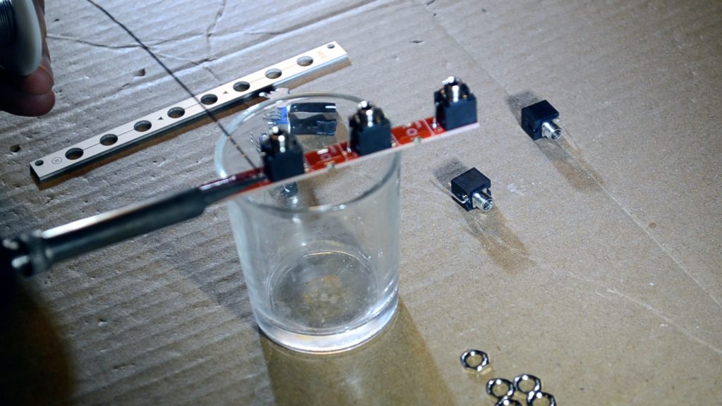
- First, gather your parts together, and start by placing the jacks in their place starting with T1. As you place each jack, solder the ground lug from the top. Continue from the top down until all jacks are soldered.
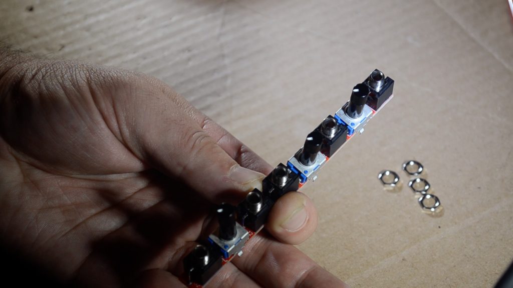
- Now place the three B100K potentiometers, but don't solder them yet. Put them in place on the PCB, and then put on the faceplate and screw in a few nuts. This will help keep the potentiometers in shape.
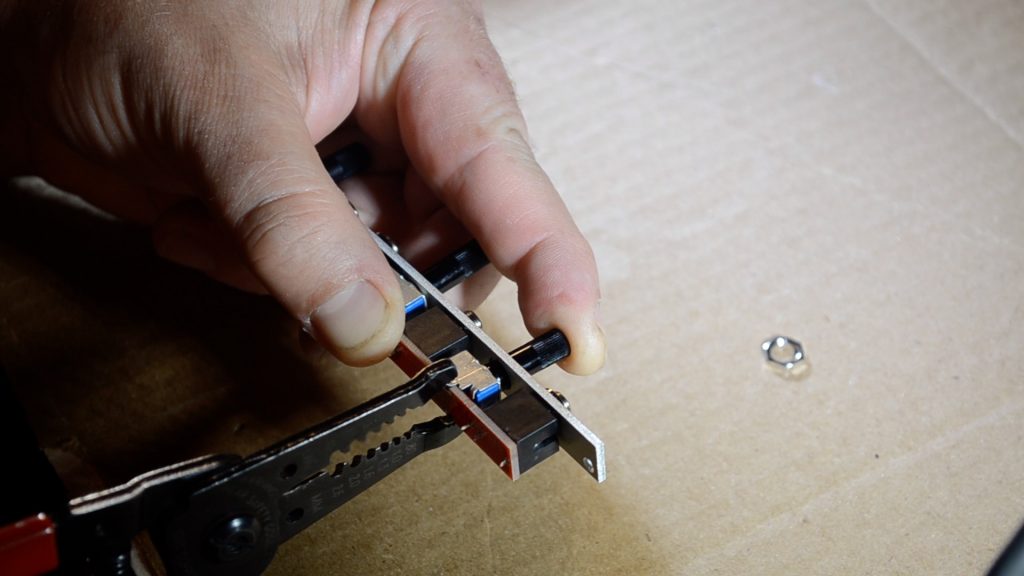
- Make sure that the potentiometer moves smoothly, and once in place, use wire strippers to fold in the tabs of the pot. Watch the build video if you have any questions.
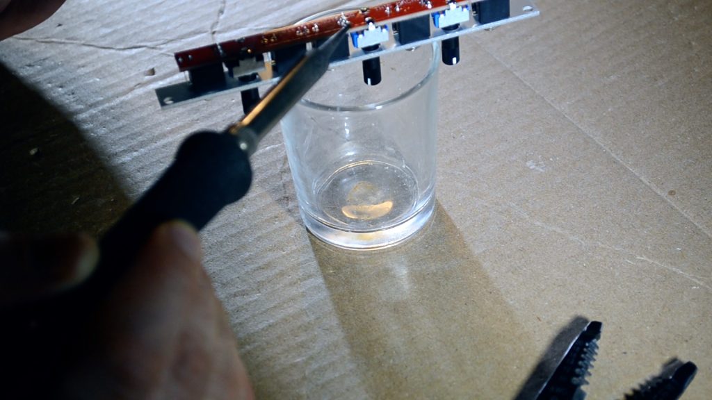
- Now turn the PCB over and solder all parts. You're done!
- Share your build on Facebook and Instagram!
- If you are having any issues at all, please contact me at: https://aisynthesis.com/contact/.
- First, gather your parts together, and start by placing the jacks in their place starting with T1. As you place each jack, solder the ground lug from the top. Continue from the top down until all jacks are soldered.
-
-