
How to Build the AI011 DIY Analog VCO
This is the build guide for the AI011 Eurorack DIY Analog VCO Module
Table of Contents
- Resources
- About the AI011 Eurorack DIY Analog VCO
- Tools Needed
- BOM (Bill of Materials)
- Build Guide
1. Resources
2. About the DIY Analog VCO Module
This DIY Analog VCO uses a reissue of the famous 3340 "VCO on a chip" made by Alfa. The Curtis 3340 was the voice of legendary synthesizers by Roland, Moog, Sequential Circuits, Oberheim, and many many others. It is stable, versatile, and an excellent choice for VCO design.
3. Tools Needed
- Soldering Iron (Cheap or Nice)
- Solder
- Soldering Tip Cleaner
- Micro-Shear Flush Cutter
- SMD Tweezers
For testing and Calibration:
- Multimeter WITH Continuity Testing
- Precision Screwdriver Set
- Accurate Tuner or Computer with https://www.zeitnitz.eu/scope_en installed.
- Oscilloscope or Computer with https://www.zeitnitz.eu/scope_en installed.
- CV Keyboard or MIDI keyboard with MIDI > CV Interface
4. BOM
| Category | Part | Quantity | Designation |
|---|---|---|---|
| Capacitor | .1uF Capacitor | 6 | C3-7, C12 |
| Capacitor | 10nF Capacitor | 4 | C10-11, 13-14 |
| Capacitor | 1nF Capacitor | 1 | C9 |
| Capacitor | 10uF Capacitor | 2 | C1-2 |
| Capacitor | 1uF Capacitor | 1 | C8 |
| Diode | 1N4148 Diode | 3 | D1-3 |
| Hardware | 2x5 Pin Header | 1 | Expander |
| Hardware | Shrouded Power Header | 1 | J5 |
| Hardware | 16 Pin Socket | 1 | IC1 |
| Hardware | 14 Pin Socket | 1 | U1 |
| Hardware | 6 pin Female Header | 3 | J1-3 |
| Hardware | 6 pin Male Header | 3 | J4-6 |
| Hardware | Jack | 8 | V/O, FM, PWM, Sync, Sin, Tri, Saw, Sqr |
| Nut | Nut | 8 | |
| IC | TL074 | 1 | U1 |
| IC | Alfa AS3340 | 1 | IC1 |
| Potentiometer | 9mm Alpha Potentiometer B100K | 3 | Fine, PWMIN, FM In |
| Potentiometer | 9mm Alpha Potentiometer B10K | 1 | Frequency |
| Regulator | 79L05 -5V Regulator | 1 | IC2 |
| Regulator | 78L05 5V Regulator | 1 | IC3 |
| Resistor | 10R OR 1N5817 Diode | 2 | R1-2 |
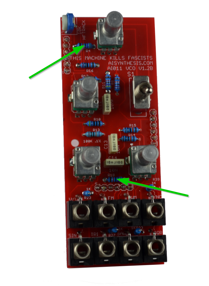
| Resistor | 470K Resistor | 2 | R4, 18 |
| Resistor | 1.8K Resistor | 1 | R6 |
| Resistor | 1.5M Resistor | 2 | R7, 12 |
| Resistor | 470R Resistor | 2 | R8, 10 |
| Resistor | 220K Resistor | 1 | R9 |
| Resistor | 47K Resistor | 1 | R11 |
| Resistor | .1% 100K Resistor | 1 | R13 |
| Resistor | 180K Resistor | 1 | R35 |
| Resistor | 200K Resistor | 1 | R16 |
| Resistor | 1M Resistor | 2 | R19-20 |
| Resistor | 5.6K Resistor | 1 | R3 |
| Resistor | 24K Resistor | 1 | R5 |
| Resistor | 100K Resistor | 8 | R14-15, 24, 29-30, 32, 36, 38 |
| Resistor | 10M Resistor | 1 | R17 |
| Resistor | 1K Resistor | 6 | R21-23, 27, 33, 39 |
| Resistor | 91K Resistor | 3 | R25, 31, 37 |
| Resistor | 240K Resistor | 3 | R26, 28, 34 |
| Switch | SPDT Switch | 1 | S1 |
| Transistor | J201 | 1 | Q1 (or use thru hole for Q2 but not both) |
| Trimmer | 10K Trimmer | 3 | Sine Amp, Sin Shape, V/O |
| Trimmer | 10K Horizontal Trimmer | 1 | HF Tracker |
5. Build Guide
https://youtu.be/1G2WdwJs6eg
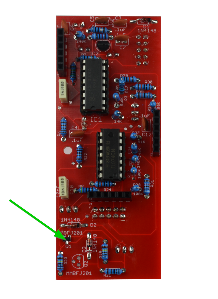
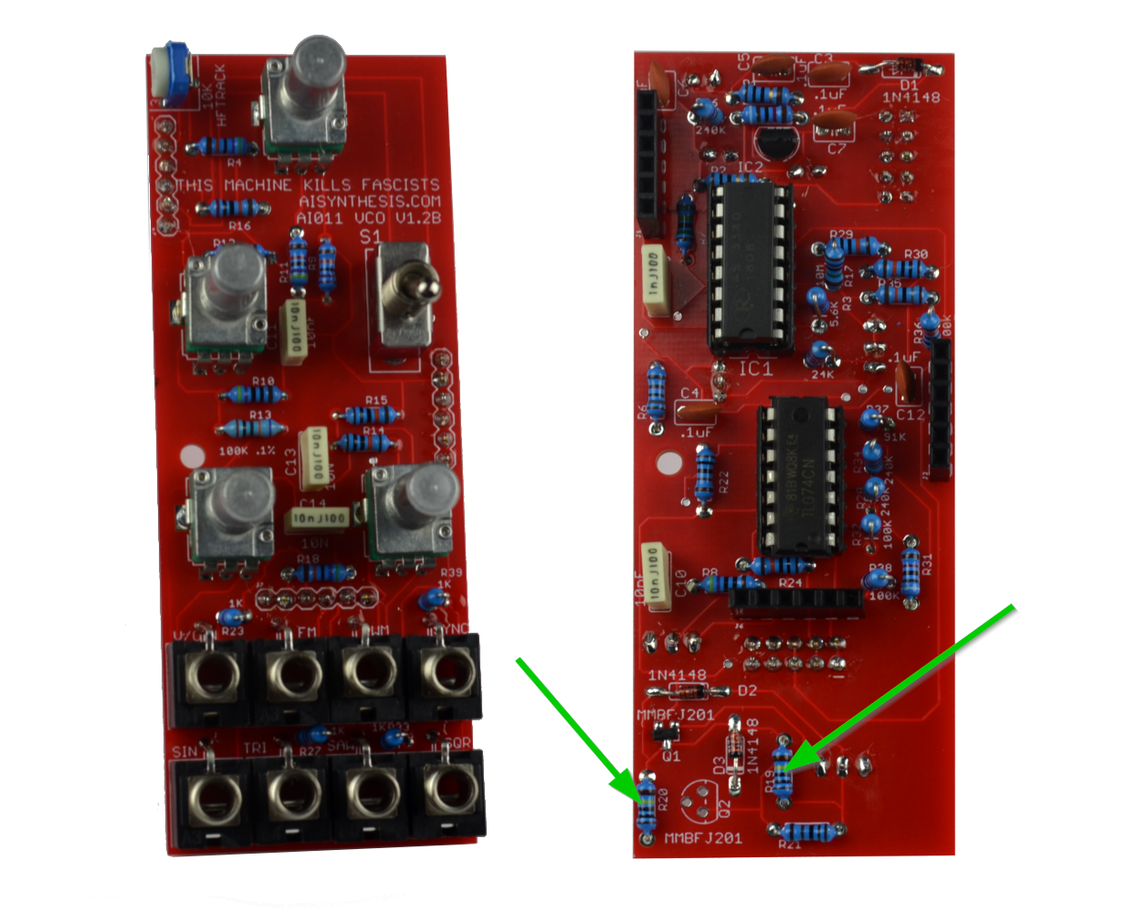
- First, solder the J201. The Kit comes with an SMD version, but if you want to you can source a thru hole one at Q2. Only use one transistor though! To solder the SMD, I usually place a small (small!) dab of solder to one of the pads, then place the transistor with tweezers, and solder that pad, and then do the others. See the video for more information.
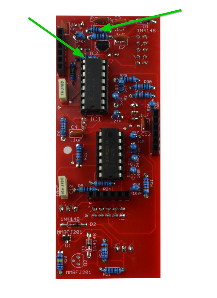
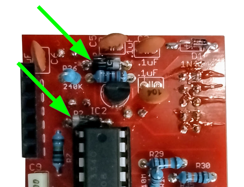
- Start by soldering the two 10R resistors OR 1N5817 Diodes at R1 and R2. Your kit may have either part, and both are fine. The kits are transitioning to using 1N5817 Diodes instead of 10 Ohm resistors for further reverse power protection. The 10 Ohm resistors are not polarized and have no orientation. The 1n5817 Diodes must be put in the correct orientation, shown below. When I re-order PCBs they will have the orientation on the PCB. I didn’t want to throw out a bunch of otherwise good PCBs.
- Now solder the two 470K resistors.
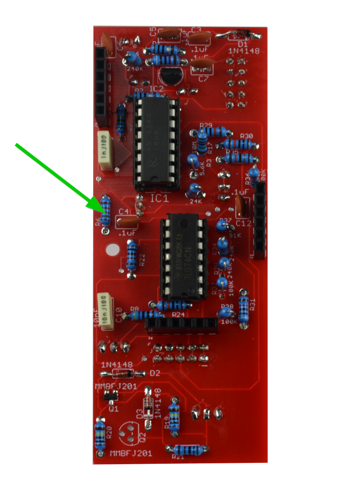
- There is one 1.8K Resistor at R6.
- There are two 1.5M Resistors at R7 and 12.

- Now solder the two 470R Resistors at R8 and 10.

- There is one 220K Resistor at R9.

- There is one 47K Resistor at R11.
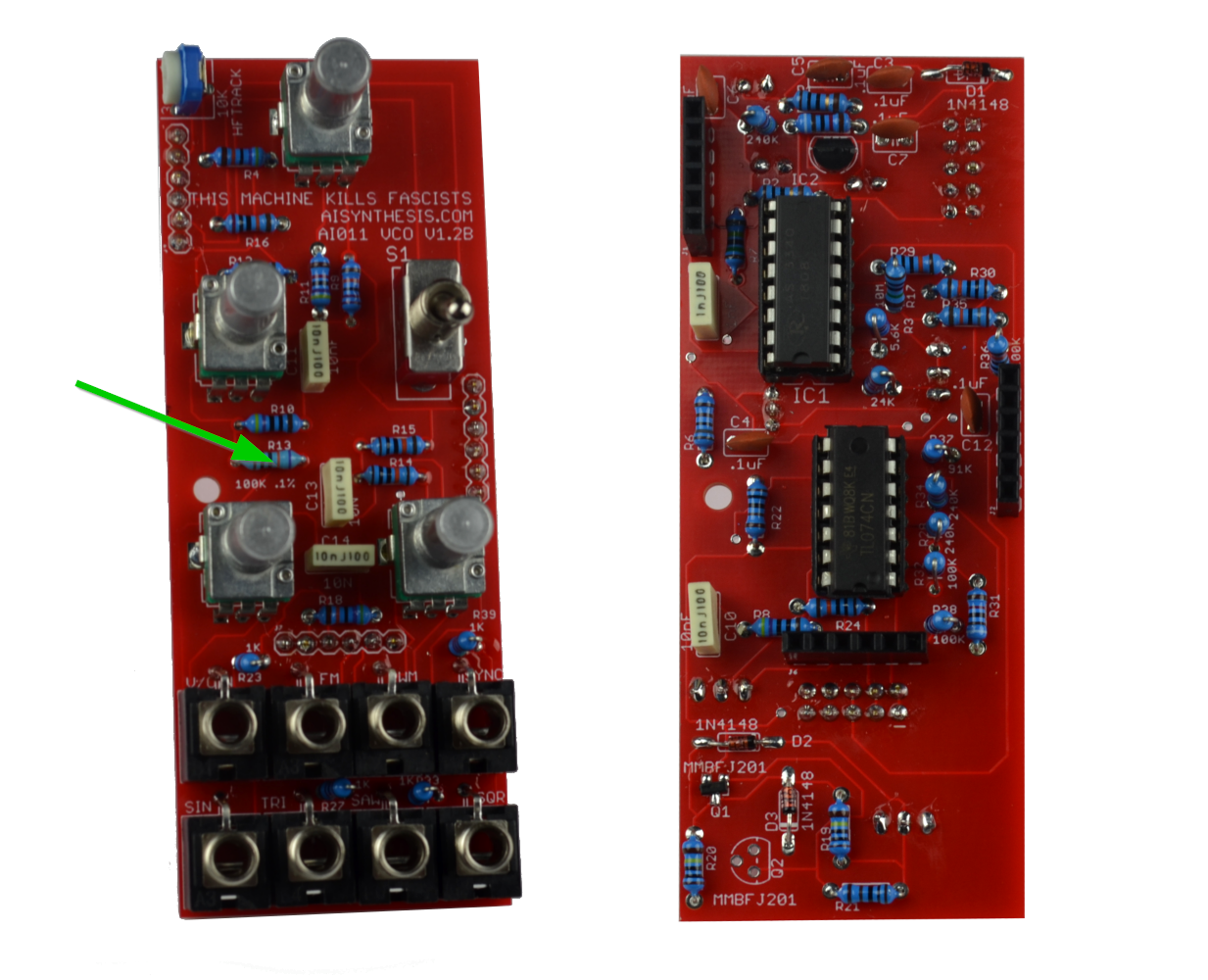
- Now solder the .1% 100K Resistor at R13. This is the input resistor for v/O, so if it isn't .1% expect wonky tracking.

- There is one 180K resistor at R35.
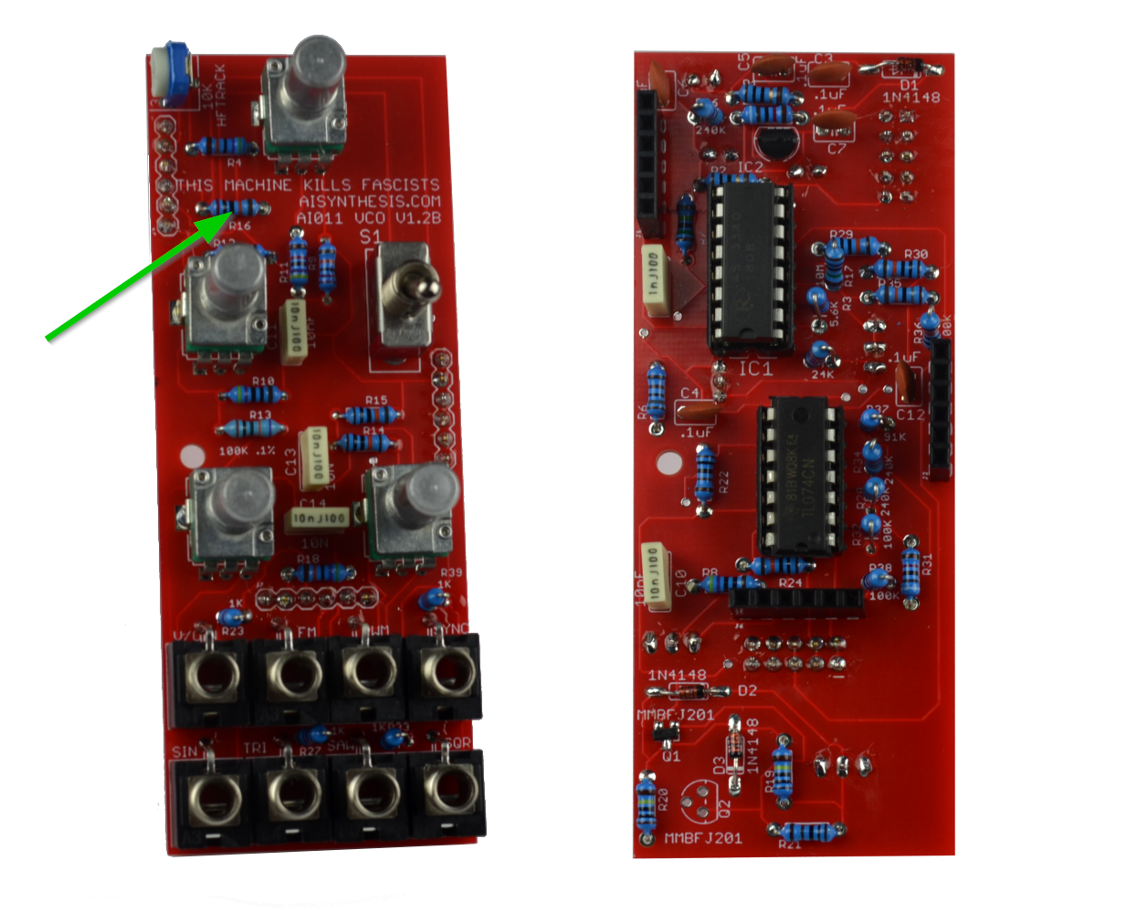
- There is one 200K resistor at R16.
- There are two 1M resistors at R19 and 20.

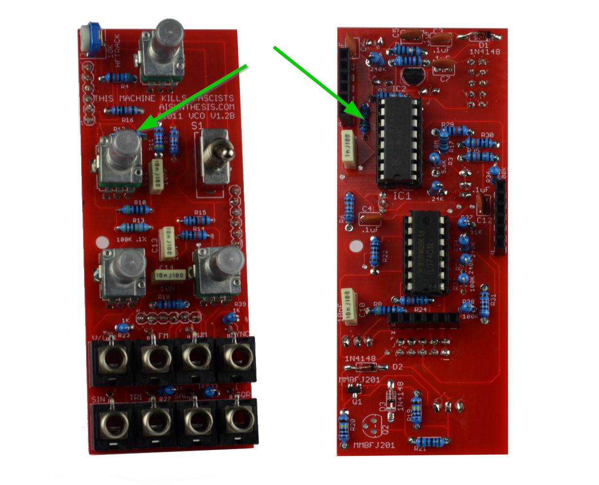
- R3 is a 5.6K standing resistor. When placing soldering resistors, consider what will be around them, especially parts with connectivity.

- There is a standing 24K Resistor at R5.
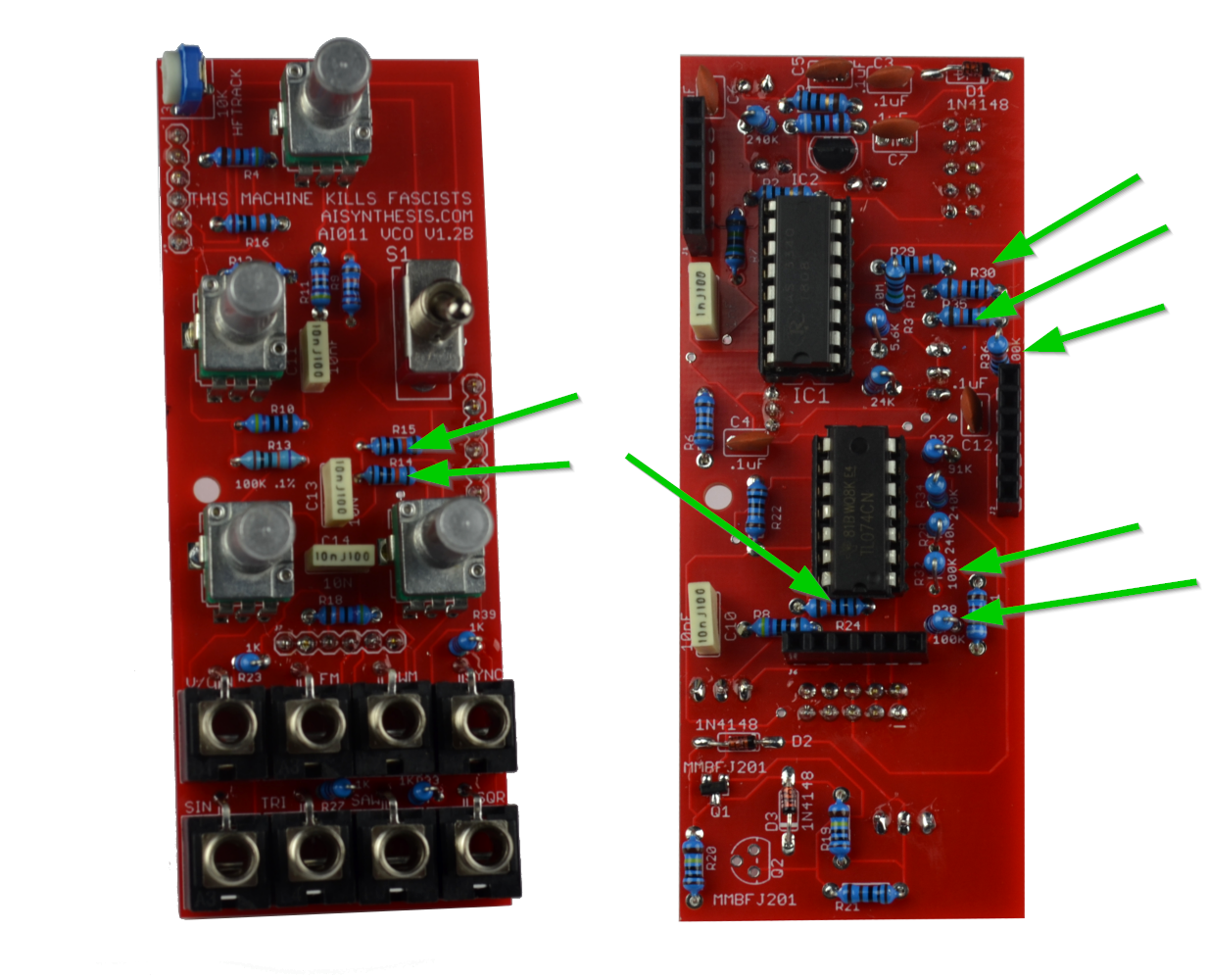
- There are 8 100K resistors. Some are standing and some are not.

- There is one standing 10M Resistor at R17.
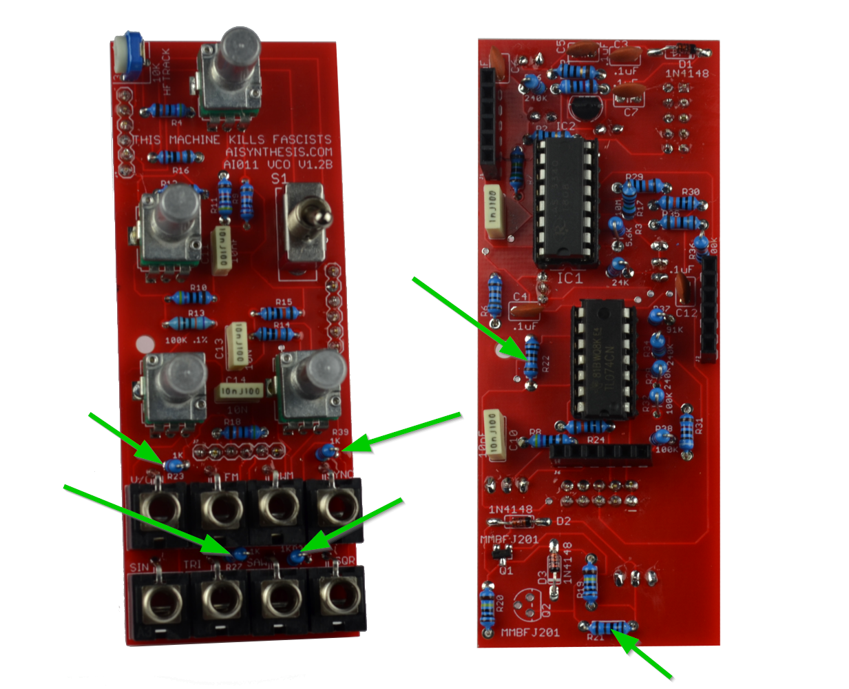
- Now for the 1K resistors. Be careful with the placement of these, especially R22, 23, 33, and 39. Ensure that the exposed leg of the standing resistor does not face the hole for the ground lug of the pot. See the image above.

- There are three 91K resistors, one of them is standing.

- There are three 240K standing resistors.
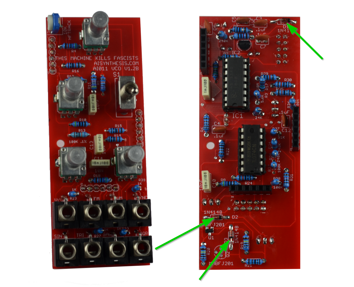
- We're done with resistors! There are three Switching diodes.
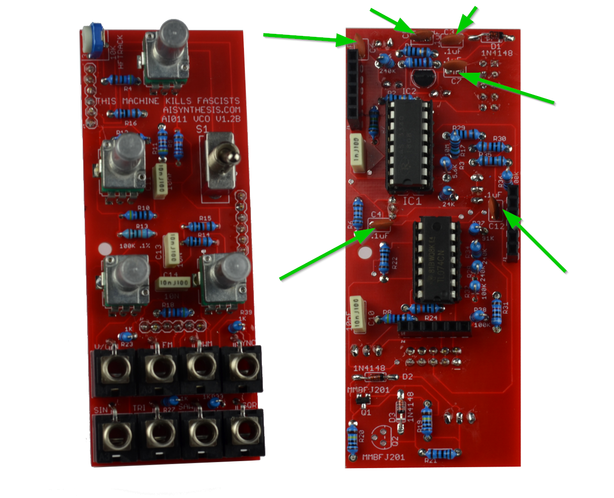
- There are 6 .1uF capacitors.

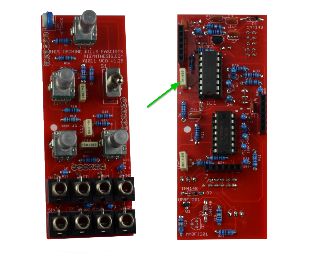
- There are four 10nF capacitors.
- There is one 1nF cap at C9.

- Now solder the 79L05 which will supply -5V to the circuit. Ensure that the Regulator alignment matches the silkscreen.
- Now solder the un-shrouded header at the expander port. DO NOT apply power to this.
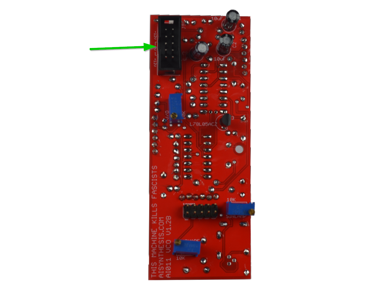
- Now solder the shrouded header. Mind the orientation. You will apply power to this.
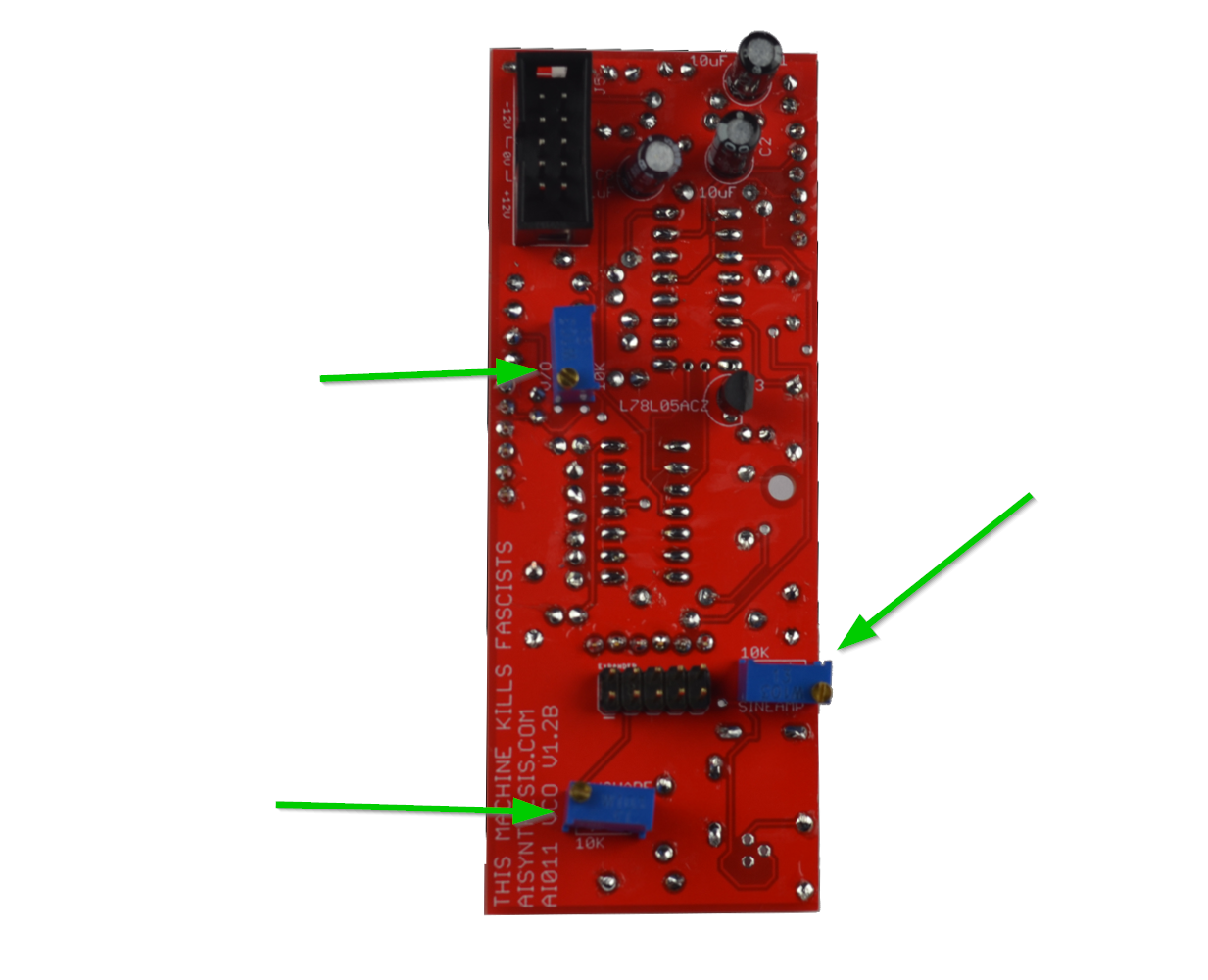
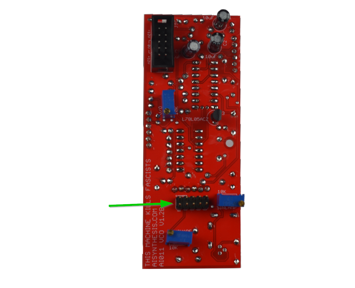
- Now solder the three 10k Trimmers on the back.
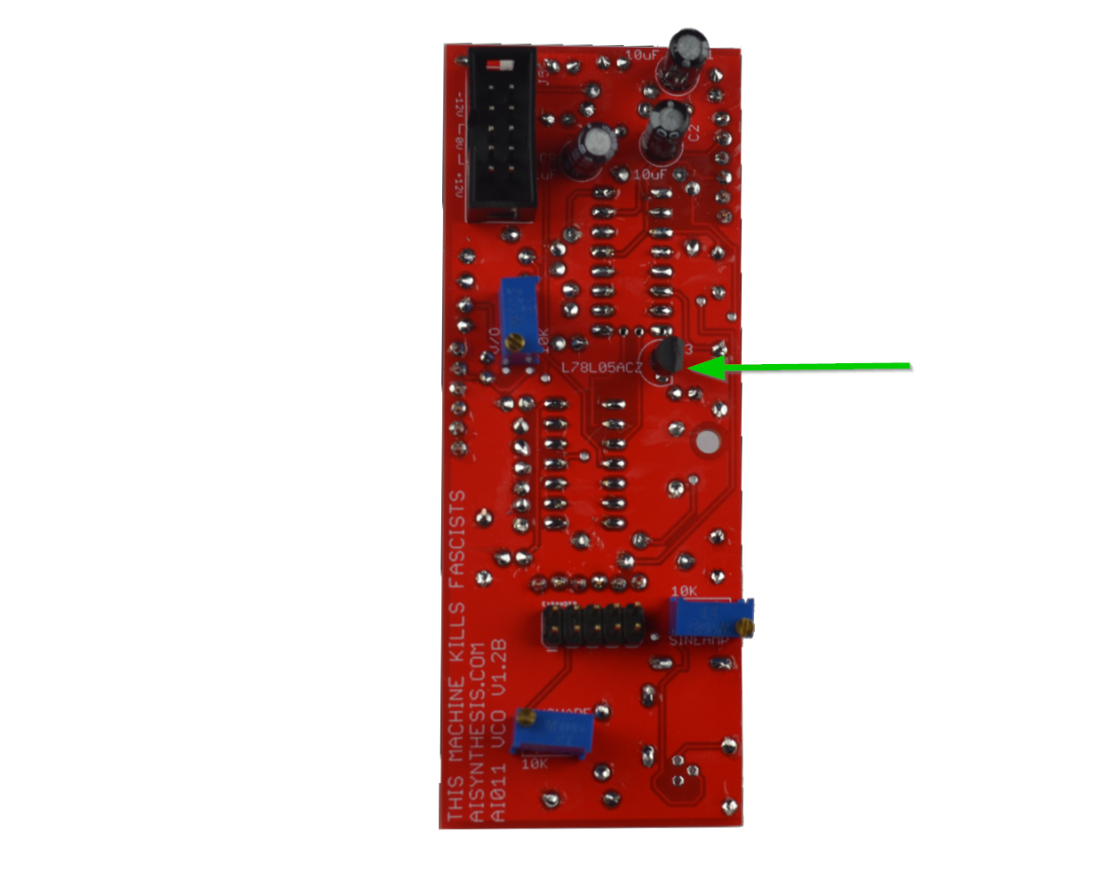
- Now solder the 78L05 which will supply +5V to the circuit. Ensure that the part aligns with the silkscreen.
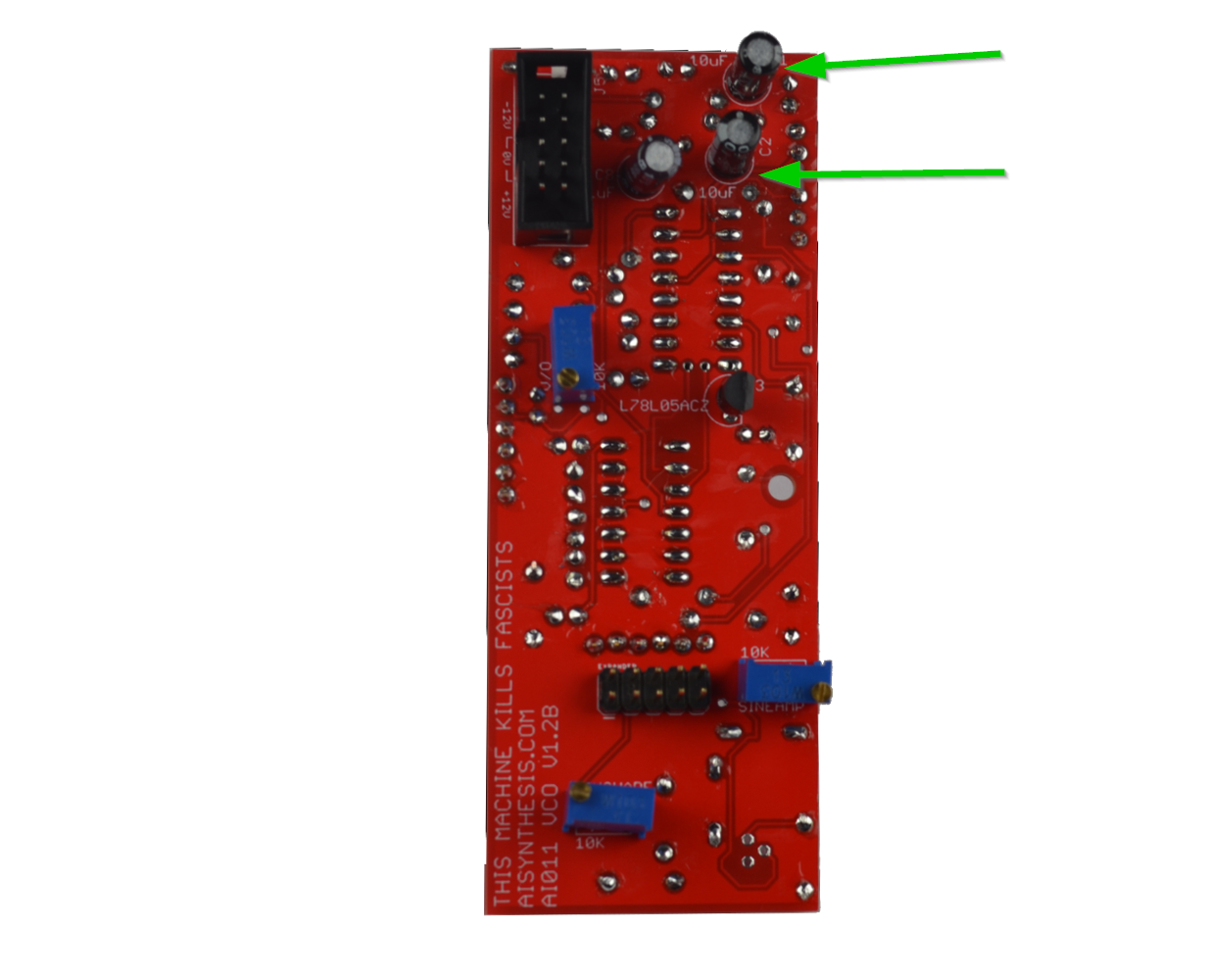
- Now solder the two 10uF caps (minding the orientation) which will smooth out power.
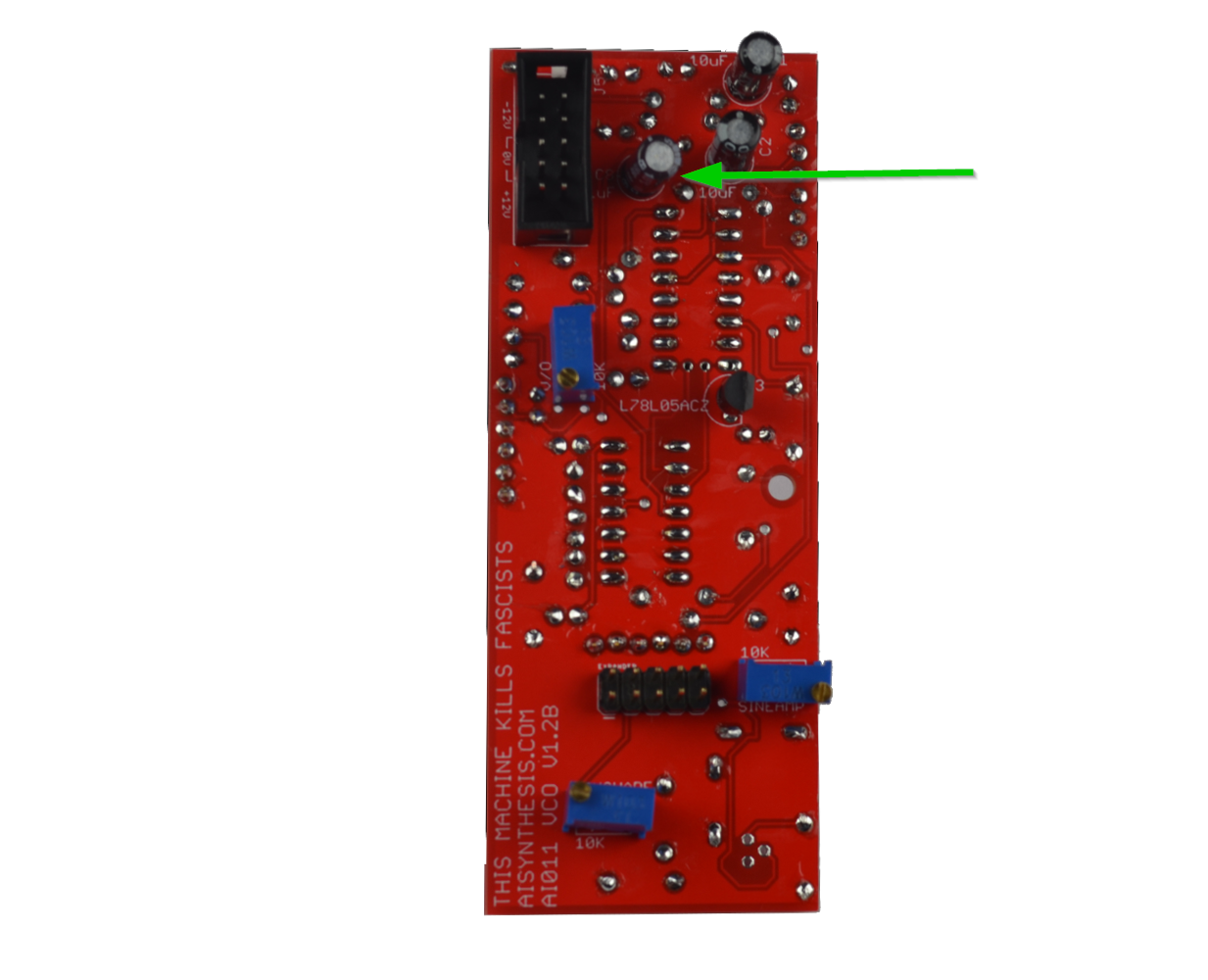
- Finishing up the rear of board B, solder the single Electrolytic 1uF Cap.
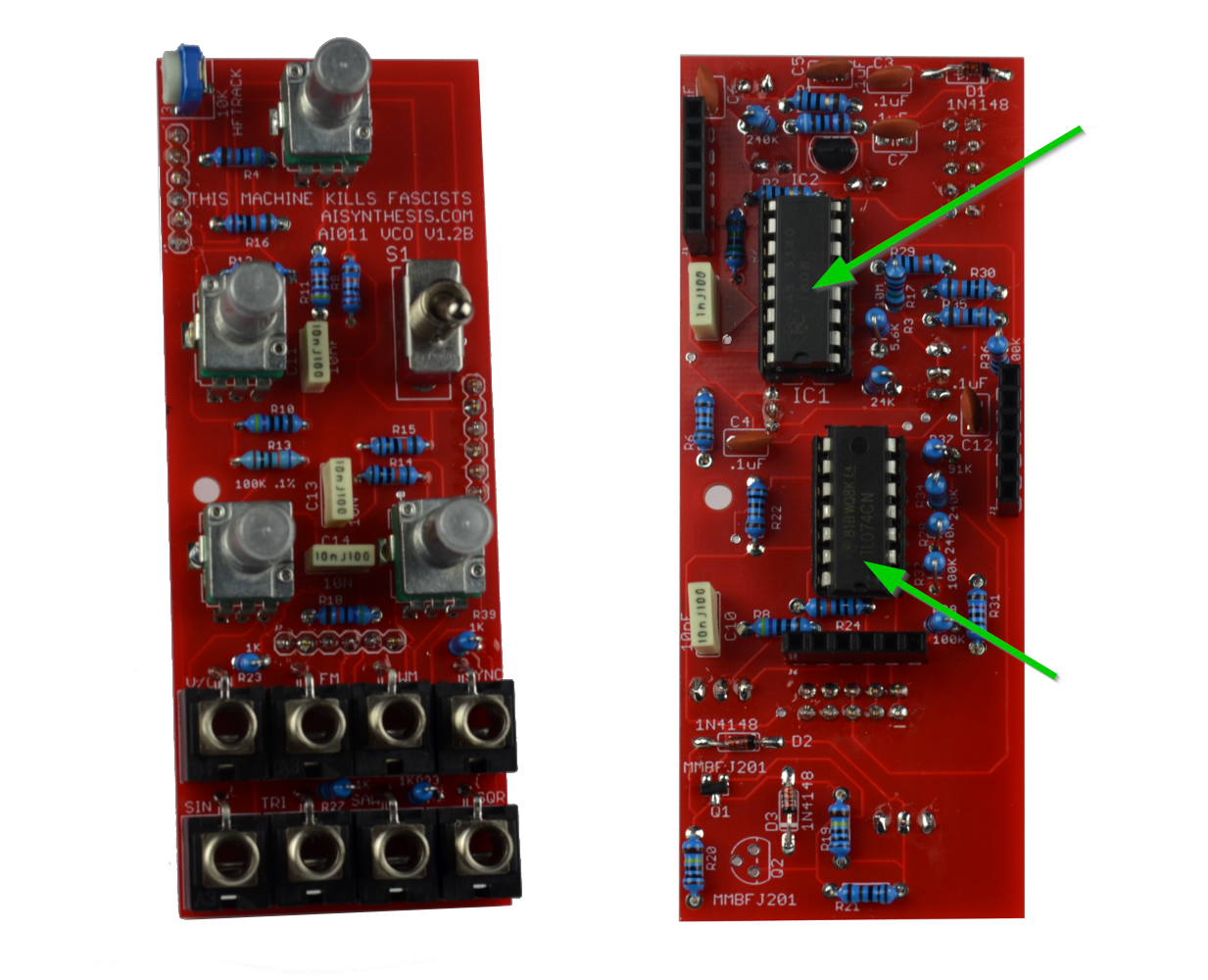
- Solder the two IC sockets, but don't place chips just yet. You might want to test power before risking expensive ICs. Ensure that the divot in the socket aligns with the silkscreen to help you ensure that the ICs are placed properly.

- We're in the home stretch! Solder the Horizontal 10K Trimmer, which is used to adjust High Frequency Tracking.
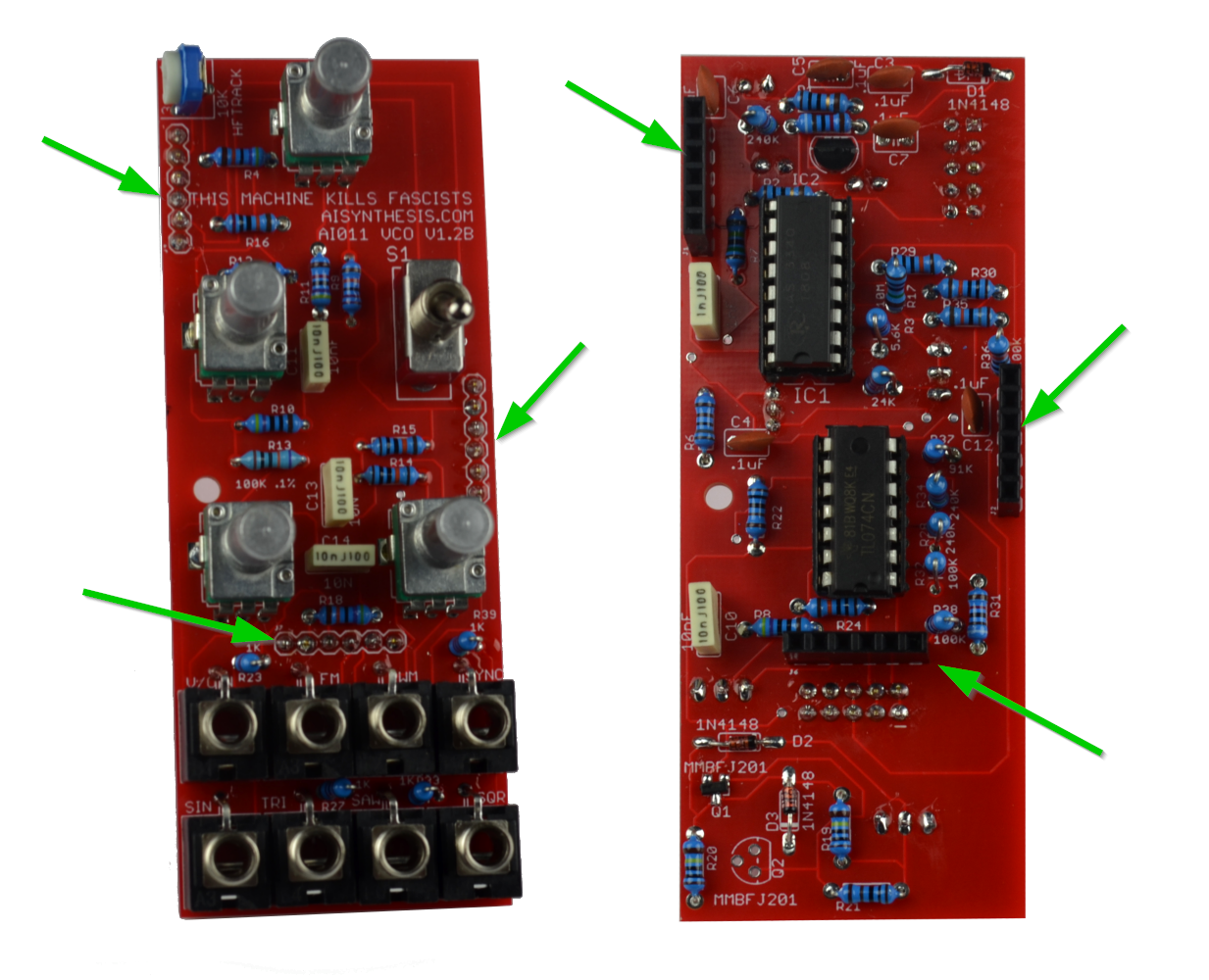
- Now solder the 6 pin header sets. It is easiest if all "male" headers are on one PCB and all "female" headers on the other. I like to connect them prior to soldering in order to ensure they are straight.

- Now carefully place and solder the three B100K pots at Fine, PWMIN, and FMIn.

- Now solder the 10K Pot at Frequency.

- Now solder in the SPDT switch. It will be snug. If you are having trouble fitting it, the switch pins might be slightly bent. If so, use Wire Strippers
to gently bend a pin into place and try to fit again.
- Now solder the 8 jacks. It is easiest to start with the bottom row of four, soldering the ground lug (the one that sticks out) from the top of the PCB, and then doing the same with the top four. Then flip the PCB over and solder all lugs and re-flow ground lugs if necessary.
- Now test Continuity on the power pins, and if there are none, apply power and test the power points before inserting ICs. If you want to measure the waveform pins, this is what I get from a working AI011: Saw: Multimeter DC: 3.95V, ~0-7 on a scope
Triangle: Multimeter DC: 1.88V, ~0-4 on a scope
Pulse: Multimeter DC: 8.9V, ~0-11 on a scope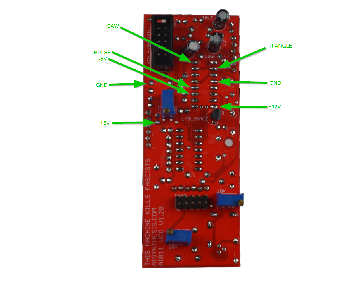
- If all is well. Turn off power, insert ICs, and begin the warm up process. Wait 30 minutes before calibrating for best results.
Calibration
The 3340 is nice and stable, making calibration pretty easy, as long as steps are followed in order. For best results, I suggest using a linear bench power supply to power the module while tuning. My main rack uses a switching supply (and a lot of digital modules), and I was/am able to tune much faster with the module being powered by a linear supply.
A New Calibration Tool
Adam Wonak made this amazing tool:" https://vco-calibration.web.
Manual Calibration
The first step is to calibrate the lower octaves. You will need either a CV Keyboard, or a MIDI Keyboard and accurate MIDI>CV Converter, and an accurate tuner and/or oscilloscope. If you do not have a hardware tuner or oscilloscope, these free programs do a fair enough job:
- https://www.zeitnitz.eu/scope_en
- https://www.sillanumsoft.org/ (Visual Analyzer) PC
- http://rs-met.com/freebies.html (Signal Analyzer) PC
- MOscilloscope (Mac/PC)
The Keyboard/Voltage should go into v/Octave of the oscillator, and the Triangle Output should go to the tuner.
The actual given frequency at a given voltage is not important, but I still like to locate C2 on the given keyboard, and tune the oscillator to show C2 when that key/voltage is present at 1V/Octave.
Once you can measure the Frequency of the oscillator when C2 is pressed, take note on paper as to the frequency. We’ll call this Frequency A. Now press C1. It will likely not be in tune. That is ok - take note of the frequency. We’ll call this Frequency B. Subtract the difference and take note.
Now adjust the V/O trimmer either CW or CCW (take note of which one) and press C2. It will need re-tuning. That is ok. Take note of the frequency at C2, press C1, and take note, then subtract the difference as you did before. If the distance is greater, reverse the turn on the V/O Trimmer. If the distance is greater but still not in tune - turn the V/O trimmer further in the direction you did.
Constantly re-measure until tuning is acceptable from C1-C4. The Oscillator is capable of very accurate tuning, but some musicians prefer a less than perfectly tuned oscillator. The choice is yours, unless you are selling it - in that case, tune it rock solid. Your customers deserve the very best.
Once C1-4 are good, leave the V/Octave trimmer alone. Hit higher octaves like C5 and 6, and turn the horizontal HF Trimmer until they are as in tune as they’ll get. It should be pretty darn close.
Sine Wave Calibration
The 3340 has ramp, pulse, and triangle outputs, but no actual sine output. A perfect sine wave is actually pretty hard. This oscillator uses a classic sine-shaping circuit to turn a buffered version of the triangle wave into a sine. You’ll need an oscilloscope, or the free https://www.zeitnitz.eu/scope_en program.
The first step is to get the sine wave trimmer to +/- 5V. Use the Sine Amp trimmer to trim the sine wave to about +/-5V. The amplitude will change depending on shape, so you don’t need it perfect just yet.
Adjust the Sine Shape trimmer until the sine shape is to your liking. Once you like the shape, trim the amp again to get it to +/5 - it should pretty much be there. Hey are we done?! I think so! Nice work!
Share your build on Facebook and Instagram!
If you are having any issues at all, please contact me at: https://aisynthesis.com/contact/.