
How to Build the AI008 Eurorack Matrix Mixer Module
This is the build guide for the AI008 Eurorack Matrix Mixer
Table of Contents
- Resources
- About the AI008 DIY Matrix Mixer
- Tools Needed
- BOM (Bill of Materials)
- Build Guide
1. Resources
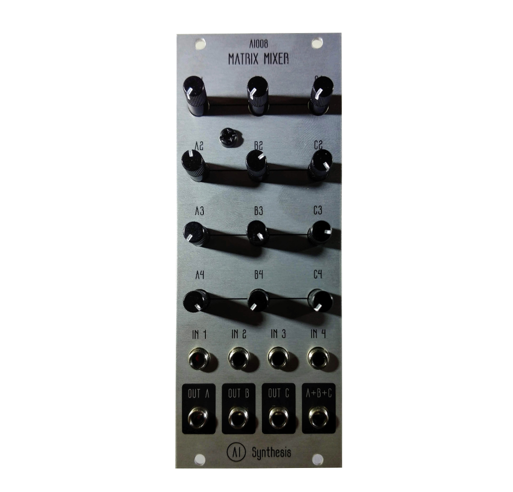
2. About the DIY Matrix Mixer
If you are new to DIY electronics, this is an ideal second module to build. This will teach you how to solder, and familiarizes the builder with the concepts of signal and ground. This DIY Matrix mixer will expand the number of inputs and outputs that can be mixed together.
3. Tools Needed
- Soldering Iron: Cheap
or Nice
- Solder
- Soldering Tip Cleaner
- Wire Strippers
- Diagonal Cutters
- Precision Screwdriver Set
4. BOM
| Category | Part | Quantity | Designation |
|---|---|---|---|
| Capacitor (Electrolytic) | 10uF Capacitor | 2 | C1, C2 |
| Capacitor | .1uF Capacitor | 4 | C3-6 |
| Hardware | 14 Pin IC Socket | 2 | U1, U2 |
| Hardware | Power Header | 1 | Power |
| Hardware | 4 Pin Female Header | 2 | J1,3 |
| Hardware | 4 Pin Male Header | 2 | J2,4 |
| Hardware | Jack | 8 | |
| Hardware | Nut | 8 | |
| Hardware | M3x10 spacer | 2 (and 4 3mm screws). | |
| IC | TL074 | 2 | U1, U2 |
| Potentiometer | A100K | 12 | |
| Resistor | 10R OR 1n5817 Diode | 2 | R1, 2 |
| Resistor | 100K | 25 | R3-17, 19-21, 23-25, 29-32 |
| Resistor | 1K | 4 | R18, 22, 26, 27 |
| Resistor | 47K | 1 | R28 |
5. Build Guide
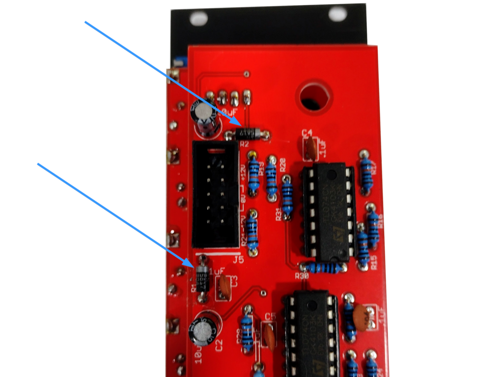
- First, gather your parts together, and start with the two 10R resistors OR 1N5817 Diodes at R1 and R2. Your kit may have either part, and both are fine. The kits are transitioning to using 1N5817 Diodes instead of 10 Ohm resistors for further reverse power protection. The 10 Ohm resistors are not polarized and have no orientation. The 1n5817 Diodes must be put in the correct orientation, shown below. When I re-order PCBs they will have the orientation on the PCB. I didn't want to throw out a bunch of otherwise good PCBs.
- Now place and solder the four 1K resistors. Note that the R26 says "100K" but it must be 1K or your Output A volume will be reduced.
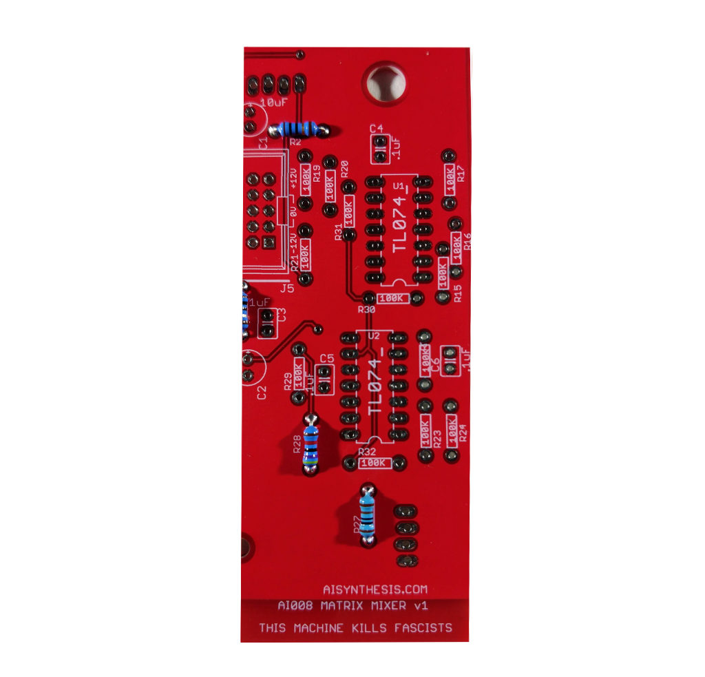
- Solder the 47K resistor at R28. This is the op-amp feedback resistor for the summed A+B+C output. It is lower than 100K to prevent overloading the op-amp. If you want more gain from the summed output, you can increase the resistor up to 100K, but that may cause op-amp distortion depending on how signals are mixed.
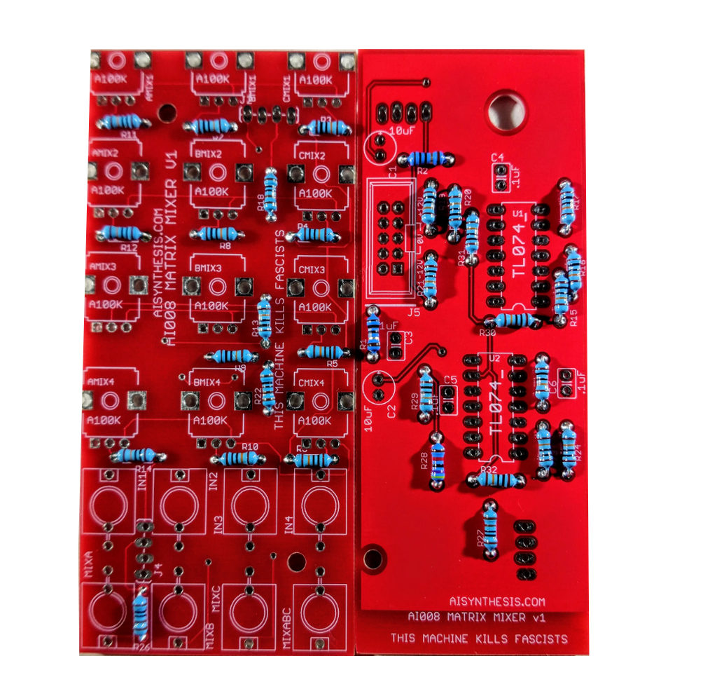
- Now place and solder the 25 100K resistors. It's a lot of resistors, but after them, you're done with them.
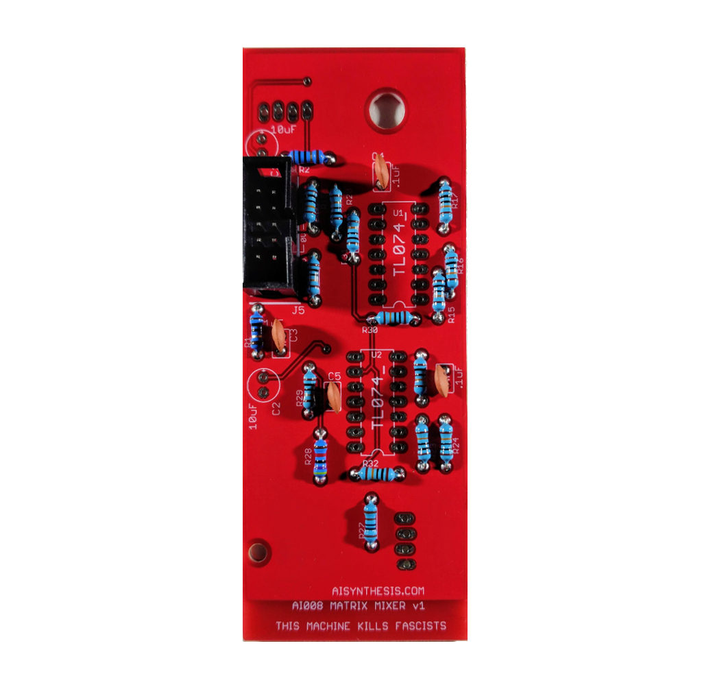
- Before we put in the .1uF capacitors that help with smoothing power, we'll solder the shrouded power header. This will help provide support while we're soldering components. Then move on to the four .1uF capacitors.
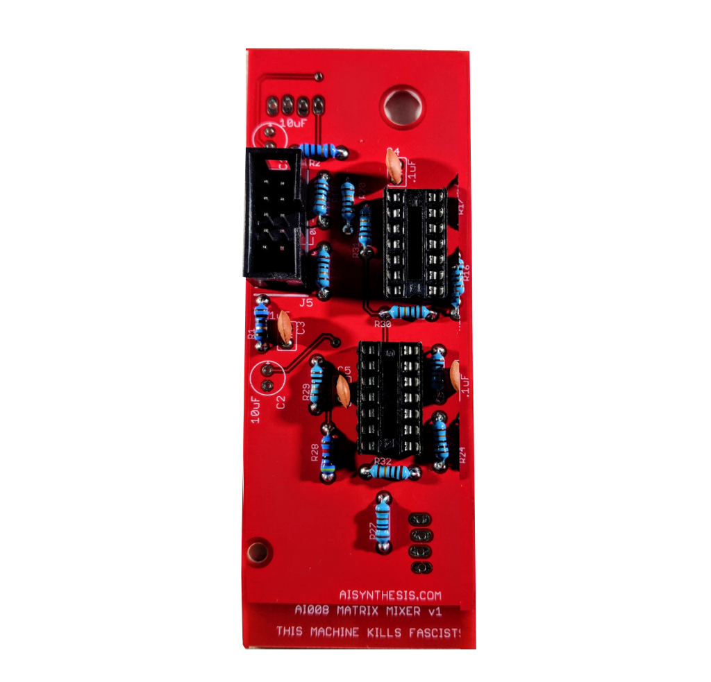
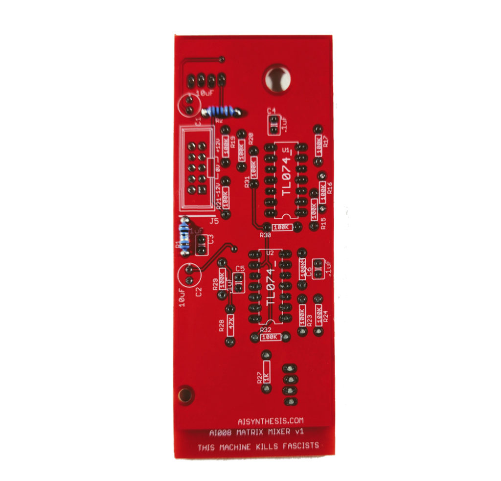
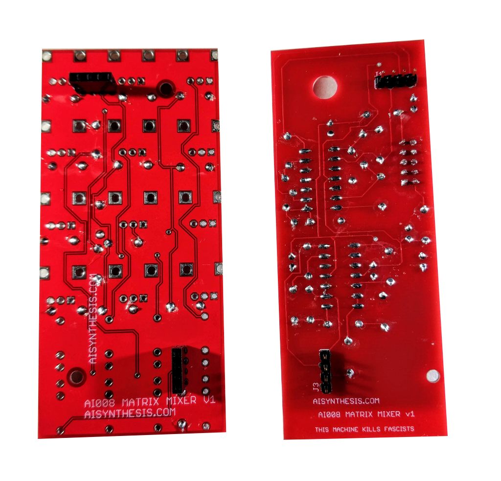
- At this point we move on to the 14 pin sockets. For clarity, ensure that the "divot" on the socket is on the same side of the silkscreen (facing down in the image above). Then we can align the ICs with the sockets and ensure that they are aligned correctly.
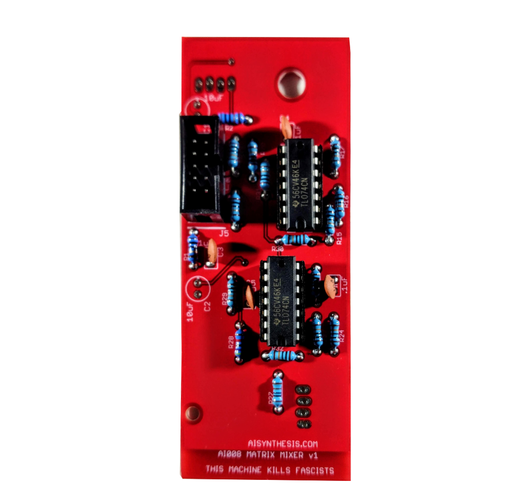
- Then insert the TL074 op amps, with the divot of the IC facing down, in alignment with the sockets and silkscreens. Ensure that the ICs are firmly socketed.
- Once the op-amps are inserted, solder in the 10uF capacitors. Mind the polarity of these components, as the positive side (no stripe) must match the "+" on the PCB.
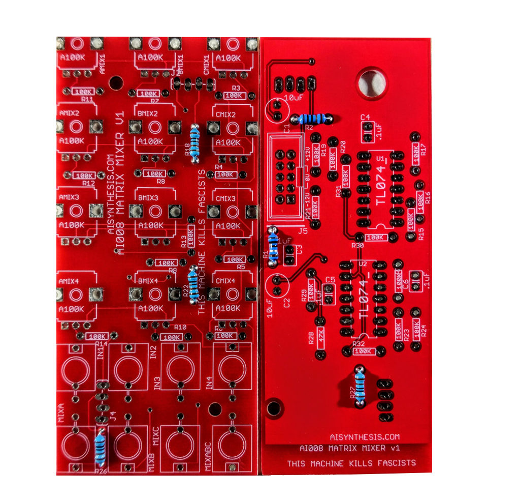
- Now insert the male and female 4-pin headers and solder them in place. I find it easiest to "plug" the headers into each other, making a PCB sandwich, and then soldering - you can view the build video if you have any questions.
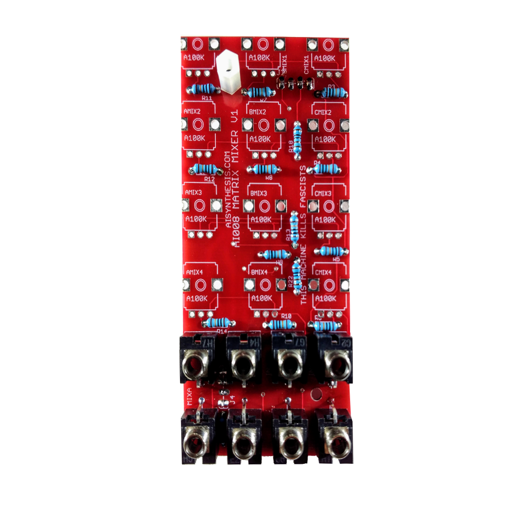
- At this point I like to attach the face plate spacer to the panel PCB (if you want you can also attach the spacer that goes to the rear PCB, or you can do that after soldering the jacks). Then solder in the jacks. I like to insert them in vertical pairs, soldering the ground lug of each (the lug that sticks out from the jack to hold them in place, flat against the PCB, and then turn them over and solder the rest of the lugs.
- With the Jacks soldered, insert the pots into the PCB, but don't solder them yet. Instead, place the Panel over the Jacks and the Pots, and screw the Panel onto the PCB/Panel spacer. This will hold the panel in place. With the panel in place, you can ensure rotation of the pots, and then turn over the PCB and solder the pots.
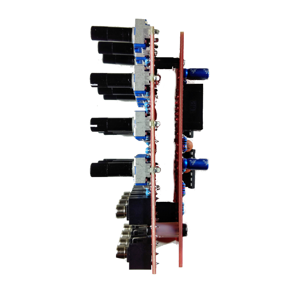
- With the Pots soldered, you can connect the two PCBs and do a continuity test, and if that checks, out, you are good to power on and test.
- Share your build on Facebook and Instagram!
- If you are having any issues at all, please contact me at: https://aisynthesis.com/contact/.