
How to Build the AI016 Tape Echo Interface
This is the build guide for the AI016 Eurorack Tape Interface
Table of Contents
- Resources
- About the AI016 DIY Tape Interface
- Tools Needed
- BOM (Bill of Materials)
- Build Guide
1. Resources
2. About the DIY Tape Interface
If you are new to DIY electronics, this is an ideal second or third module to build. The DIY Tape Interface is an adaptation of the classic Echo-Matic Tape Echo circuit for Eurorack Modular Circuits.
3. Tools Needed
- Soldering Iron: Cheap
or Nice
- Solder
- Soldering Tip Cleaner
- Wire Strippers
- Diagonal Cutters
- Precision Screwdriver Set
4. BOM
| Category | Part | Quantity | Designation |
|---|---|---|---|
| Capacitor (Electrolytic) | 10uF Capacitor | 7 | C1, 4, 5, 7, 9, 10, 13 |
| Capacitor (Electrolytic) | 220uF Capacitor | 1 | C2 |
| Capacitor | 100pF Capacitor | 4 | C3, 8, 11-12 |
| Diode | 1N4001 Diode | 1 | D1 |
| Hardware | 14 Pin IC Socket | 1 | IC1 |
| Hardware | Power Header | 1 | Power |
| Hardware | 10 Pin Socket Header | 1 | J2 |
| Hardware | 4 Pin Plug Header | 1 | J1 |
| Hardware | Jack | 4 | In, Out, Send, Return |
| Hardware | Nut | 4 | |
| Hardware | M3x10 spacer | 1 (and 2 3mm screws). | |
| IC | TL074 | 1 | IC1 |
| Potentiometer | A10K | 3 | Echo Mix, In Volume, Output |
| Potentiometer | B20K | 1 | Repeats |
| Resistor | 10K | R1,2, 10 | 3 |
| Resistor | 22K | 3 | R3, 4, 8 |
| Resistor | 1.5K | 1 | R5 |
| Resistor | 47K | 1 | R7 |
| Resistor | 100R | 1 | R6 |
| Resistor | 100K | 4 | R9, 11-13 |
| Switch | DPDT | 1 | SW1 |
5. Build Guide
https://youtu.be/E8D4pCsR7iA
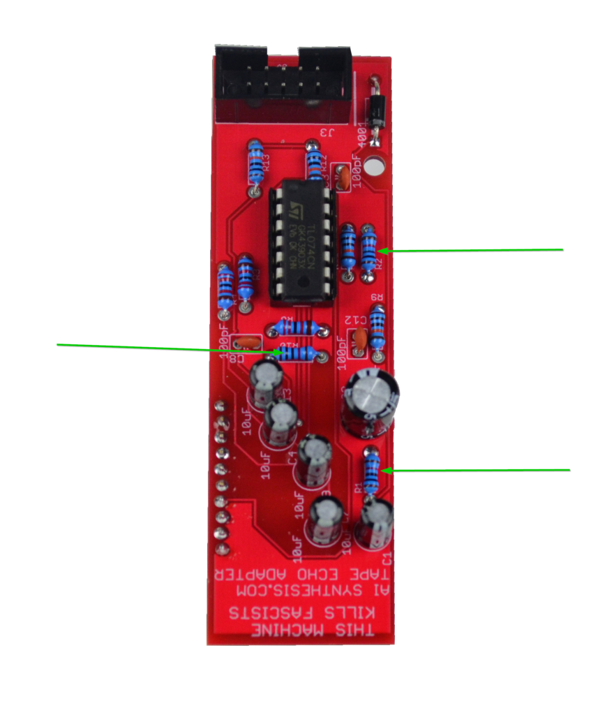
- First, gather your parts together, and start with the three 10K resistors at R1, R2 and R10.
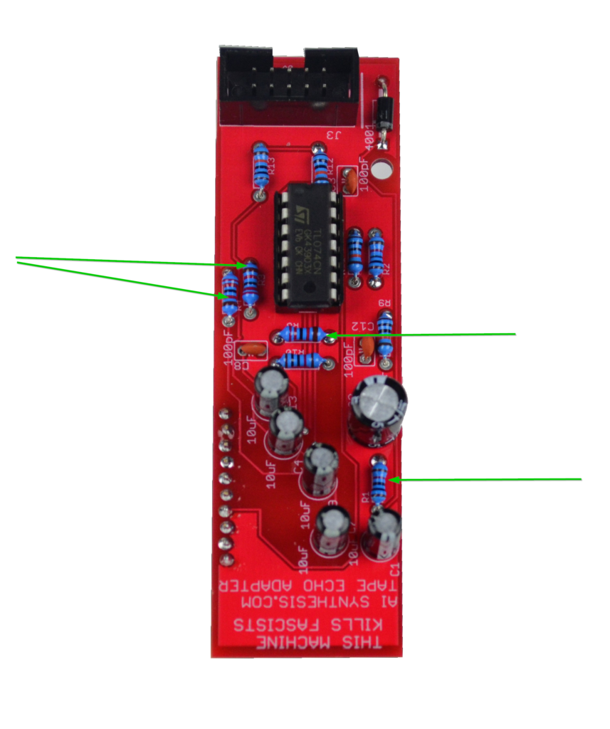
- Now place and solder the three 22K resistors.
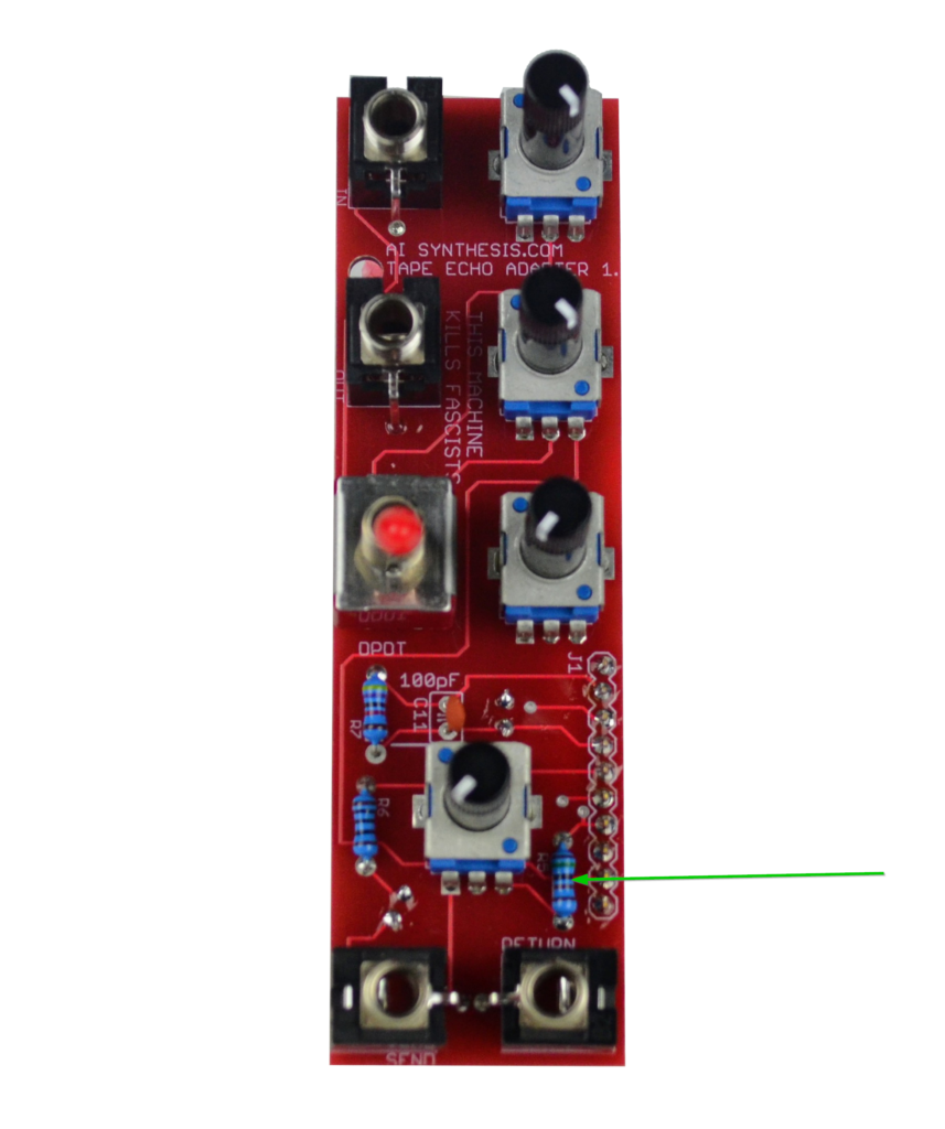
- Solder the single 1.5K resistor at R5.
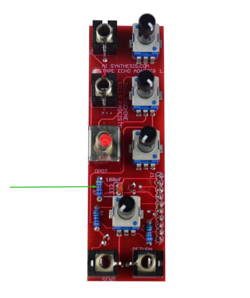
- Now place and solder the single 47K resistor at R7.
- Then solder the 100 Ohm Resistor at R6.
- At this point we move on to the 4 100K resistors.
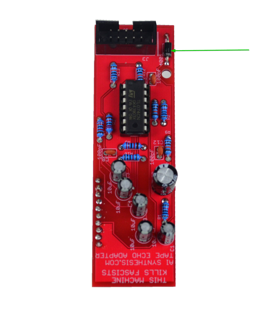
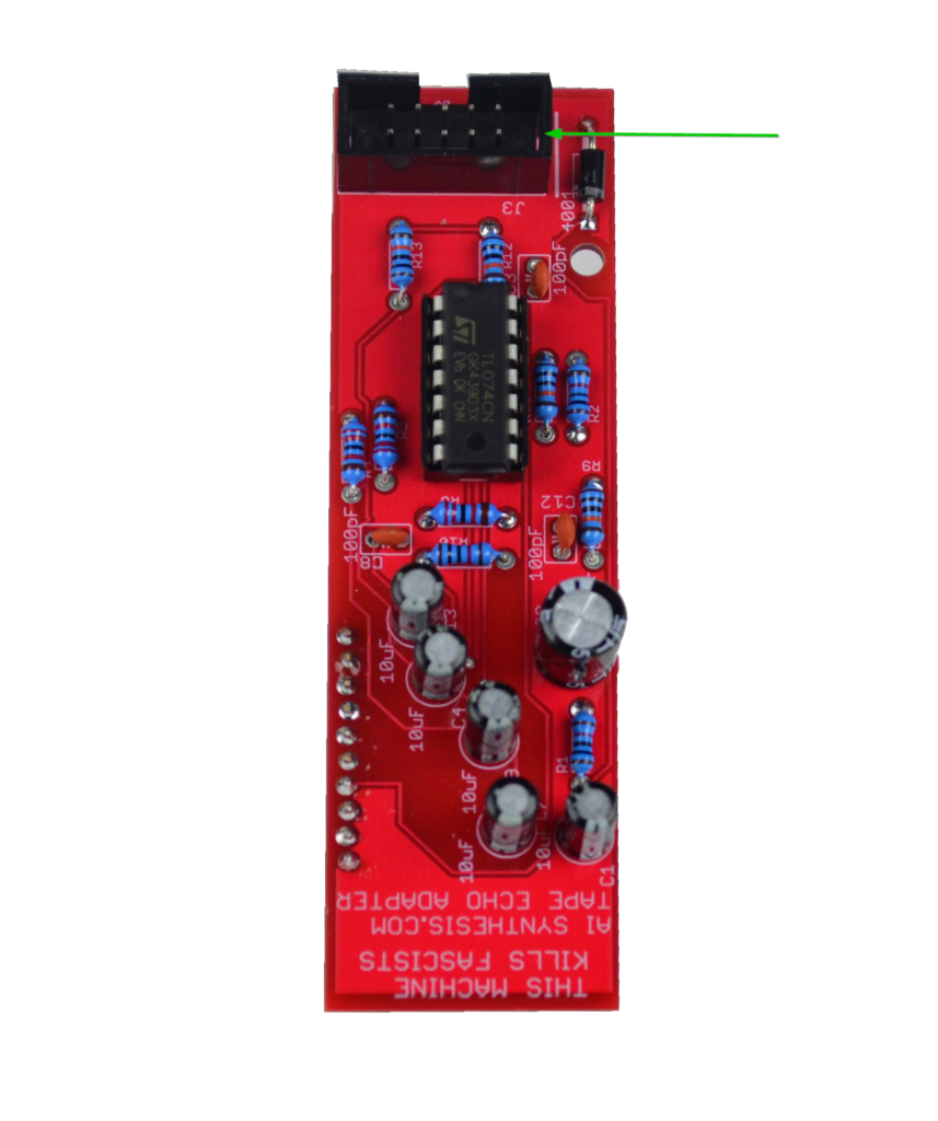
- Then solder the 1N4001 Diode. Ensure the polarity matches the silk screen. I kept this circuit as close to the original Echo Matic Tape Echo as possible so that the PCB could be used off of a positive/ground supply in case you wanted to build it into a stomp box for guitar purposes.
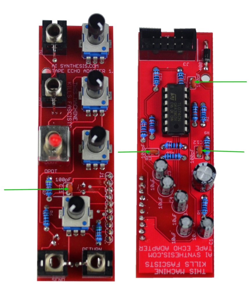
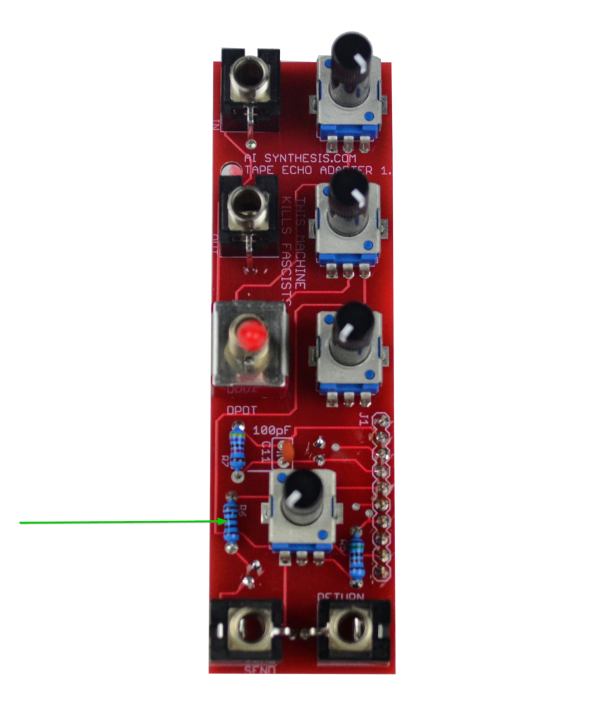
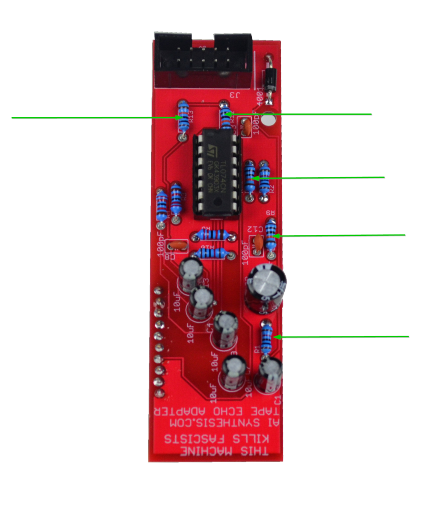
- Now solder the 4 100pF capacitors.
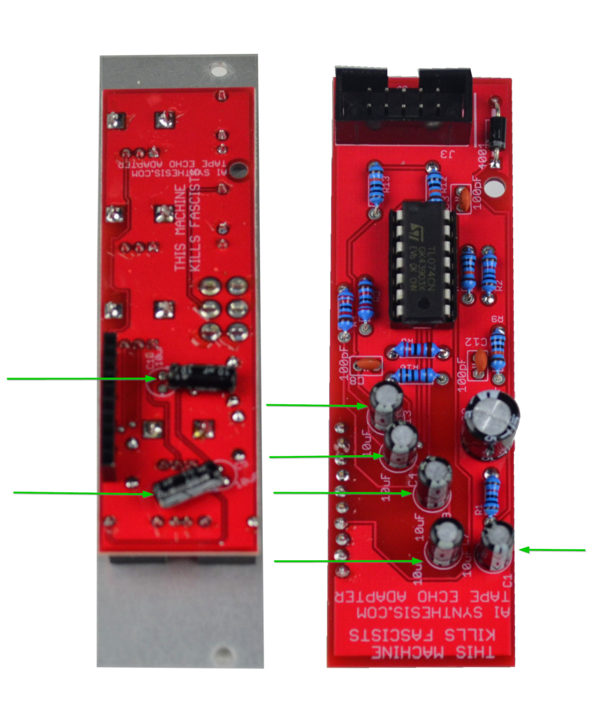
- Now solder the 7 10uF Electrolytic Capacitors. These are polarized, and two need to be bent (follow the silk screen). Most of these are to couple the signal as it goes in and out of the circuit.
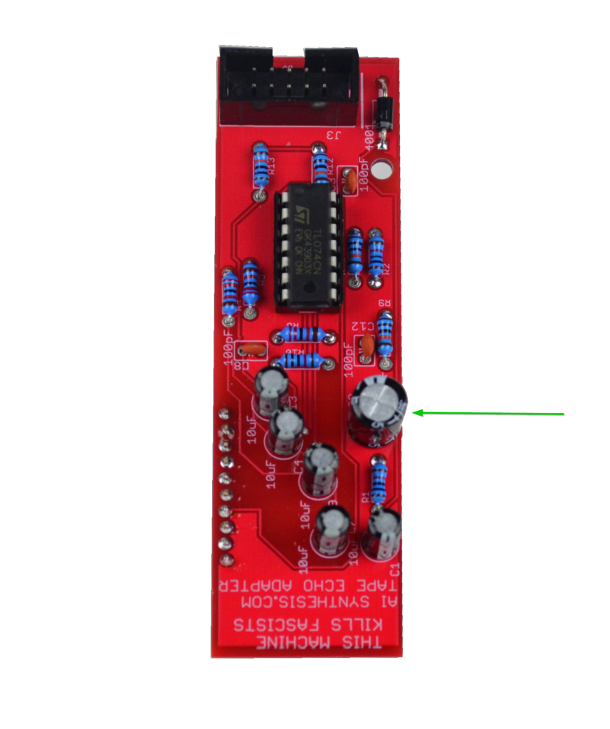
- Now solder the single 220uF Electrolytic polarized Capacitor. This is in the power supply circuit.
- Now install the shrouded power header.
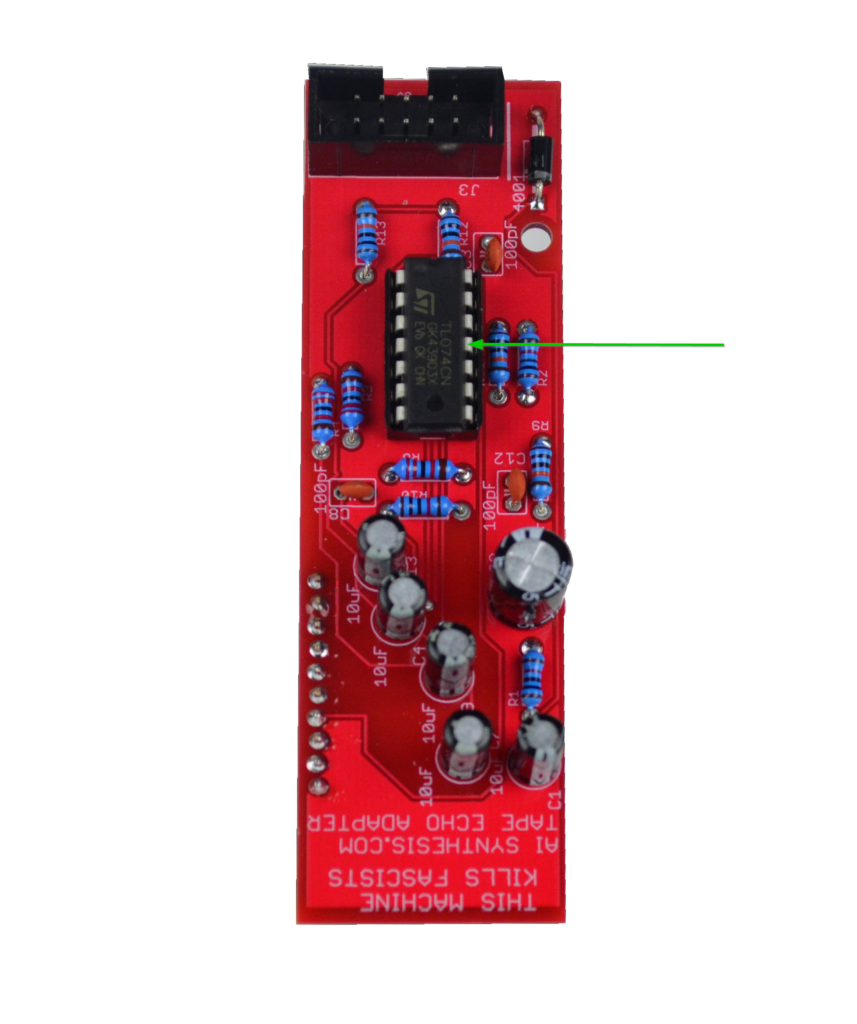
- Now insert and solder the 14 pin socket in line with the silkscreen. Once the socket is soldered, insert the IC in line with the socket.
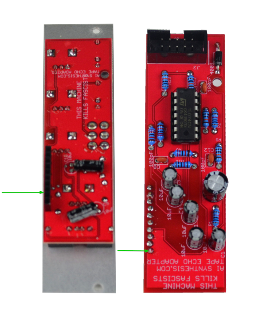
- Now insert the 10 pin plug and socket headers. Install the PCB spacer on the panel facing PCB to help with soldering. (This will also allow you to place the panel to have a straight Switch later).
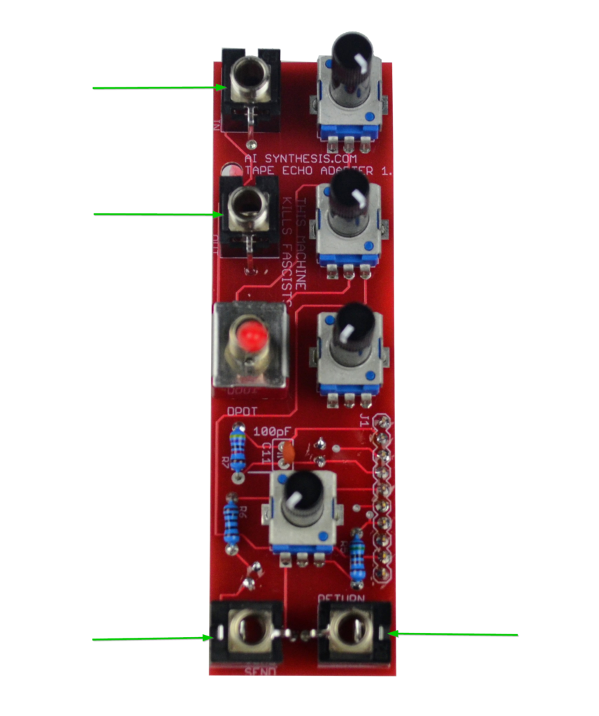
- Now install and solder the four jacks. I like to solder the ground lugs (the lugs that stick out) from the top, and then turn the PCB over to finish soldering the lugs.
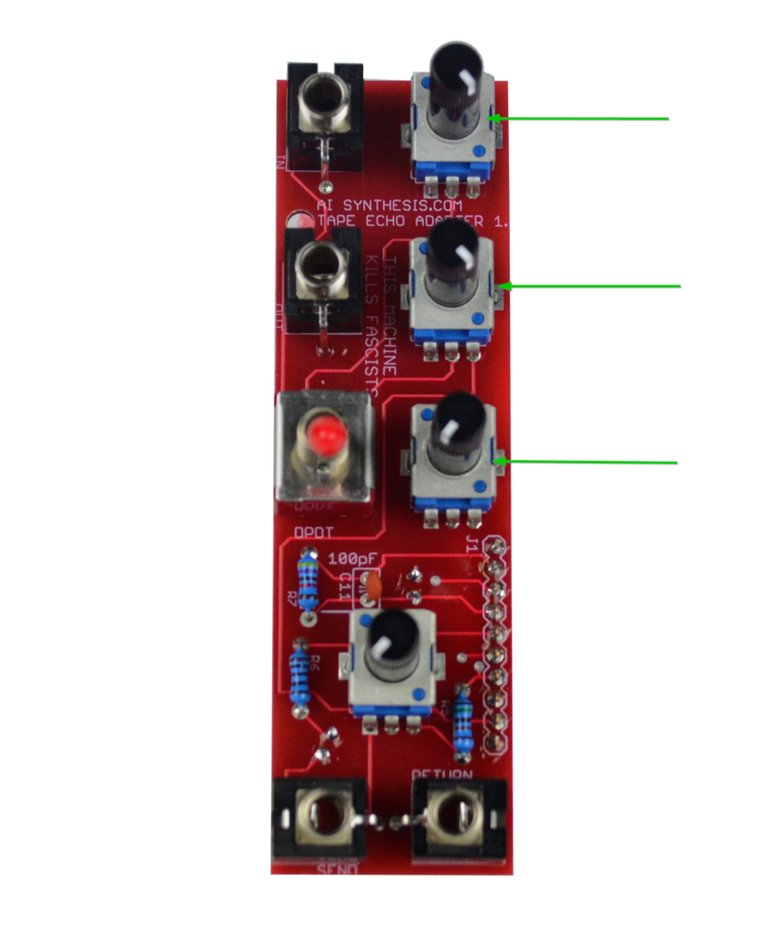
- Now solder the three A10K potentiometers.
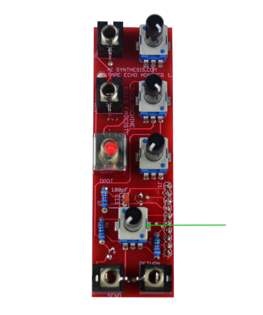
- Now solder the B20K Repeats potentiometer.
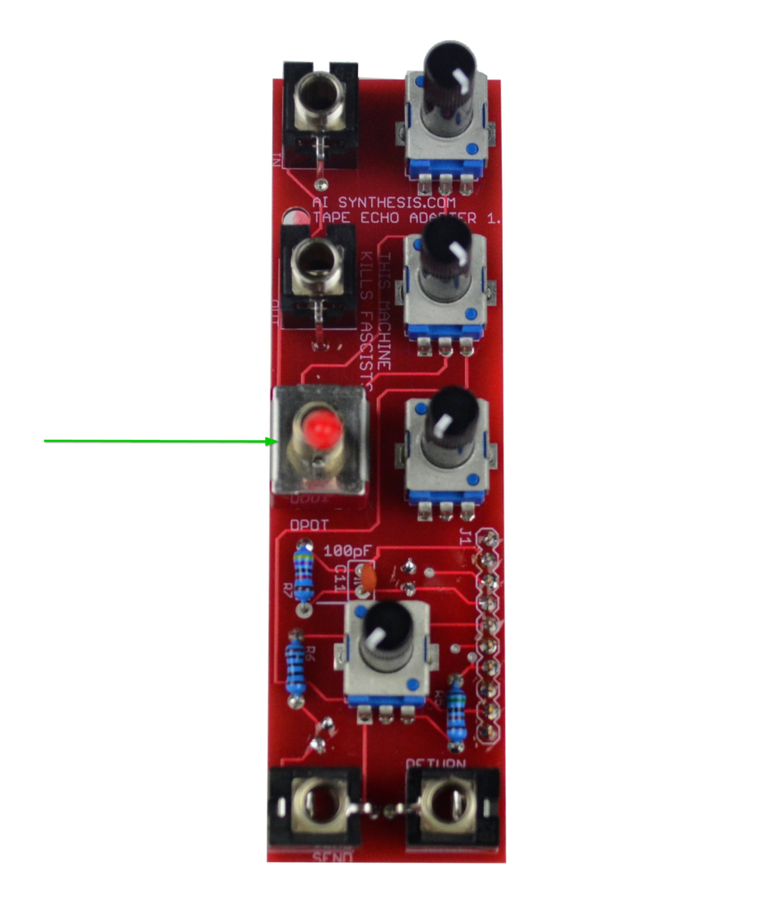
- Now solder the DPDT Switch. Place the panel on before soldering to ensure it is straight.
- Share your build on Facebook and Instagram!
- If you are having any issues at all, please contact me at: https://aisynthesis.com/contact/.