

How to Build the AI028 Voltage Controlled Matrix Mixer
This is the build guide for the AI028 Voltage Controlled Matrix Mixer
Table of Contents
- Resources
- About the AI028 DIY Stereo Matrix Mixer
- Tools Needed
- BOM (Bill of Materials)
- Build Guide
1. Resources
2. About the DIY Voltage Controlled Matrix Mixer
The AI028 DIY Voltage Controlled Matrix Mixer is a 6-input, 6-output Matrix Mixer, with 36 Linear VCAs to control how much each input is fed to each output (0-5V). The Module can distribute audio and/or control voltage, and has a dedicated 5V output for use with passive or active attenuators for manual volume control.
3. Tools Needed
- Soldering Iron: Cheap
or Nice
- Solder
- Soldering Tip Cleaner
- Micro-Shear Flush Cutter
For testing and Calibration:
4. BOM
| Category | Part | Quantity | Designation |
|---|---|---|---|
| Capacitor | 10uF Capacitor | 2 | C1-2 |
| Capacitor | 10uF Non-Polar Capacitor | 6 | C7-12 |
| Diode | 1N5817 Schottky Diode | 2 | D1, D2 |
| Hardware | Shrouded Power Header | 1 | Power |
| Hardware | Jack | 49 | A ton of 'em |
| Hardware | 14 Pin Plug Header | 4 | n/a |
| Hardware | 14 Pin Socket Header | 4 | n/a |
| Nut | Nut | 49 | Regulator | L78L05 | 1 | IC6 |
5. Build Guide
- To start, we need to make the PCB sandwich with the 14 pin headers and solder those. Be sure to reference other images in this guide to ensure the headers are on the right side of the PCB.
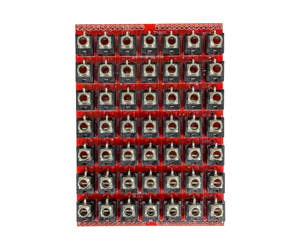
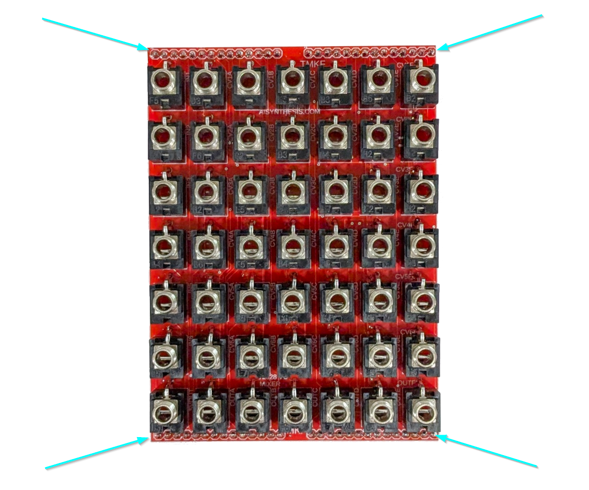
- Now solder the 49 jacks. I like to start from the bottom row and solder the ground lug (the one that sticks out) from above. Then I soft place the panel and loosly place four nuts to keep the panel in place, just to ensure the jacks are straight. Finally, I finish soldering them from the other side of the PCB. Be thorough.
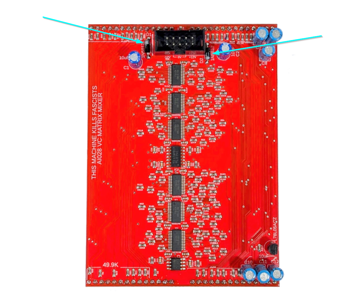
- Now solder the 2 1N5817 Diodes. These will protect the module if power is somehow reversed.
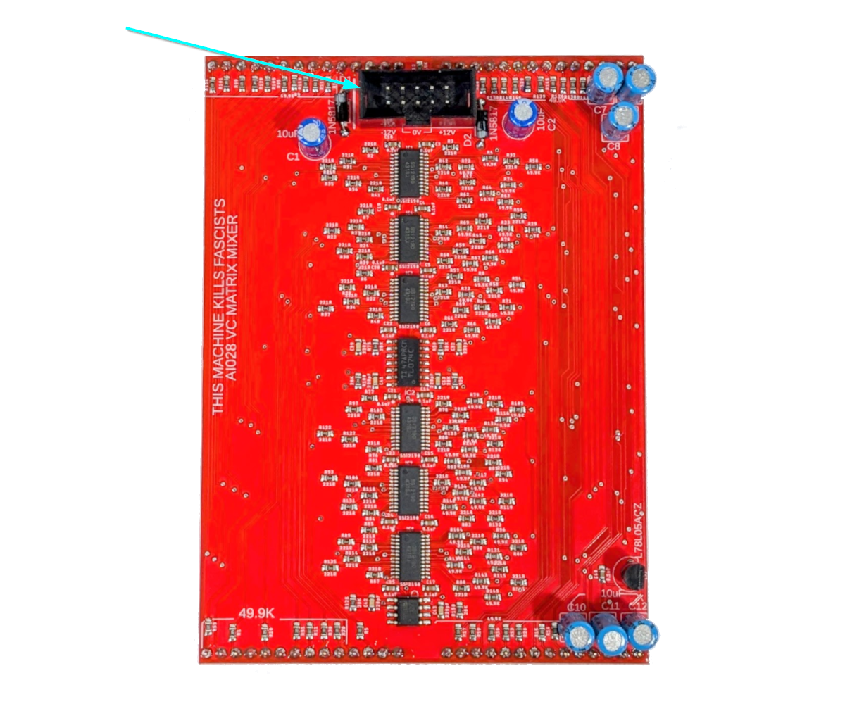
- Now solder the Power Header, which will take pressure off the caps we’re about to install.
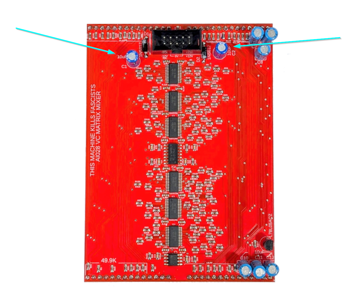
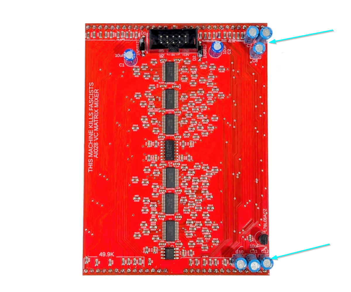
- Now solder the four 10uF caps that are part of the power filtering circuit. These caps are polarized and have a stripe, and must be oriented correctly.
- Now solder the six non-polar 10uF Capacitors. They are non polar and can go in either way.
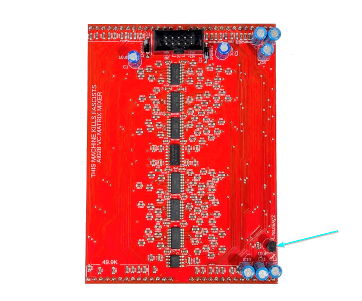
- The last step is to solder the Power Regulator as shown above. When assembling the PCBs, the jack board should have the text right side up, and the ground lugs on the jacks should be pointing up. The Power connector will be at the top.
- Now We’re done! Perform a Continuity Test and power on if there are no shorts between +, -, and GND.
Congratulations!
Share your build on Facebook and Instagram!
If you are having any issues at all, please contact me at: https://aisynthesis.com/contact/.
