
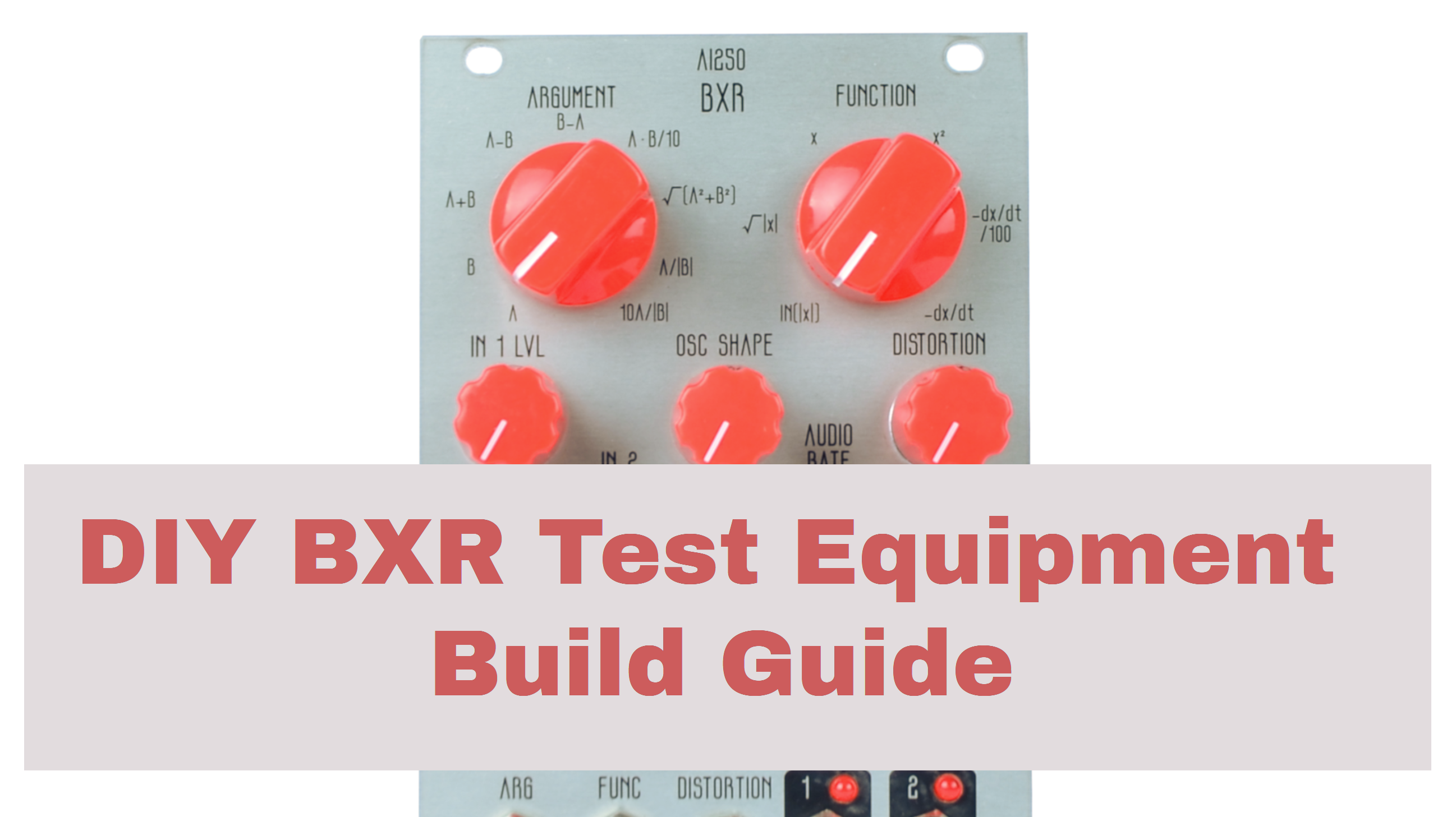
How to Build the AI250 BXR
This is the build guide for the AI250 BXR
Table of Contents
- Resources
- About the AI250 BXR
- Tools Needed
- BOM (Bill of Materials)
- Build Guide
1. Resources
2. About the DIY BXR Eurorack Test Equipment Module.
The AI250 BXR is a eurorack module inspired by vintage nuclear test equipment. It can be used as an audio mangler, cv generator, and VCO. The BXR is a nod to vintage Boxcar Averagers, which were designed to acquire and analyze fast signals. The AI250 specifically replicates the real-time mathematical portion of a Boxcar Averager System, and processes audio or cv signals against either another signal or its internal v/o variable wave-shape VCO.
3. Tools Needed
- Soldering Iron: Cheap
or Nice
- Solder
- Soldering Tip Cleaner
- SMD Tweezers
- Micro-Shear Flush Cutter
- Multimeter WITH Continuity Testing


4. BOM
| Category | Part | Quantity | Designation |
|---|---|---|---|
| Capacitor | .1uF Capacitor | 1 | C1 |
| Diode | 1N5817 Schottke Diode | 2 | D1-2 |
| Hardware | 2x5 Pin Socket | 4 | n/a |
| Hardware | Shrouded Power Header | 1 | Power |
| Hardware | Jack | 12 | J1-12 |
| IC | CD4051 | 1 | U2 |
| IC | Daisy Patch | 1 | n/a |
| LED | 3mm LED | 2 | LED 1-2 |
| Potentiometer | B10K Pot | 7 | Pot 1-7 |
| Nut | Nut | 12 | Switch | SPDT Switch | 3 | SW1-3 |
5. Build Guide
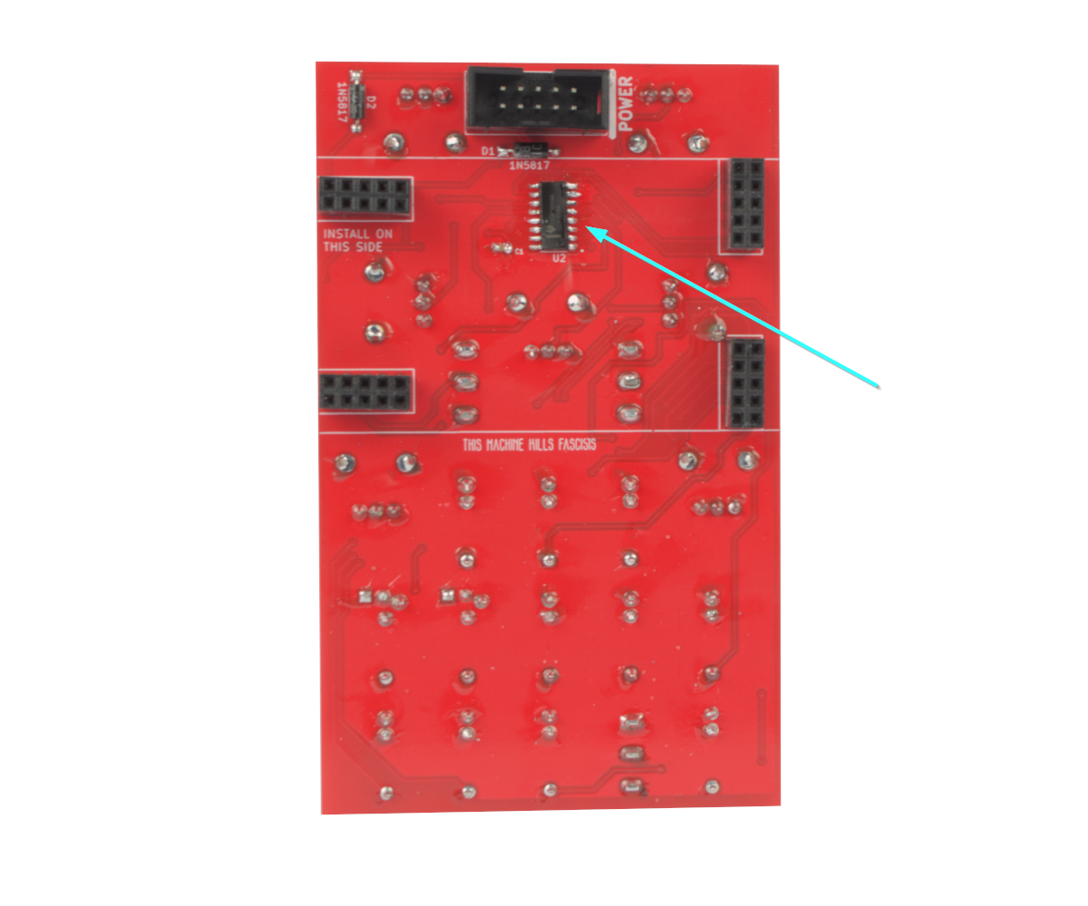
- To start, we need to solder the CD4051. Pin 1 is indicated by a white dot in the lower right corner. The chip I am using has a line, this should point downwards.
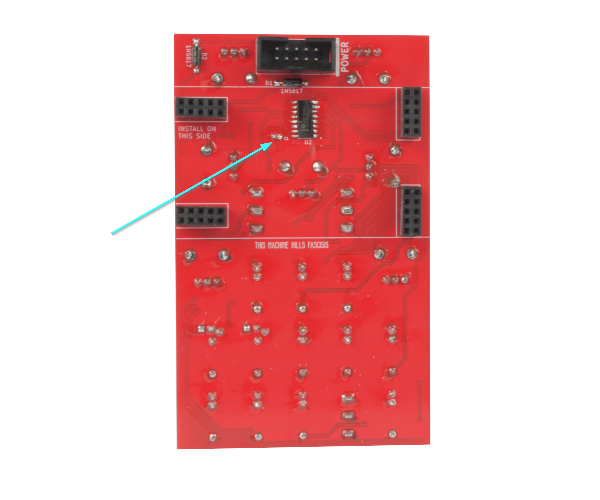
- Now solder the .1uF capacitor. Now we are done with SMD parts.
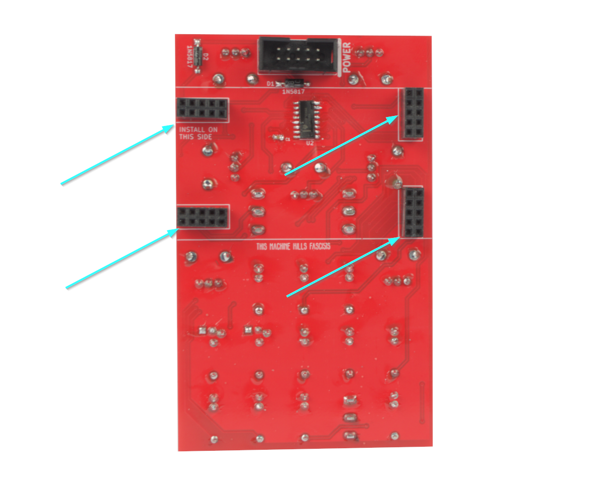
- Now solder the four 2x5 pin sockets. The trick I use, is to connect them to the Daisy seed and then connect them to the PCB and solder them in.
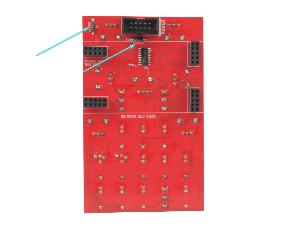
- Now solder the two 1N5817 Diodes. These will protect the module in case power is reversed. Just make sure the stripe on the diode matches the stripe on the PCB.
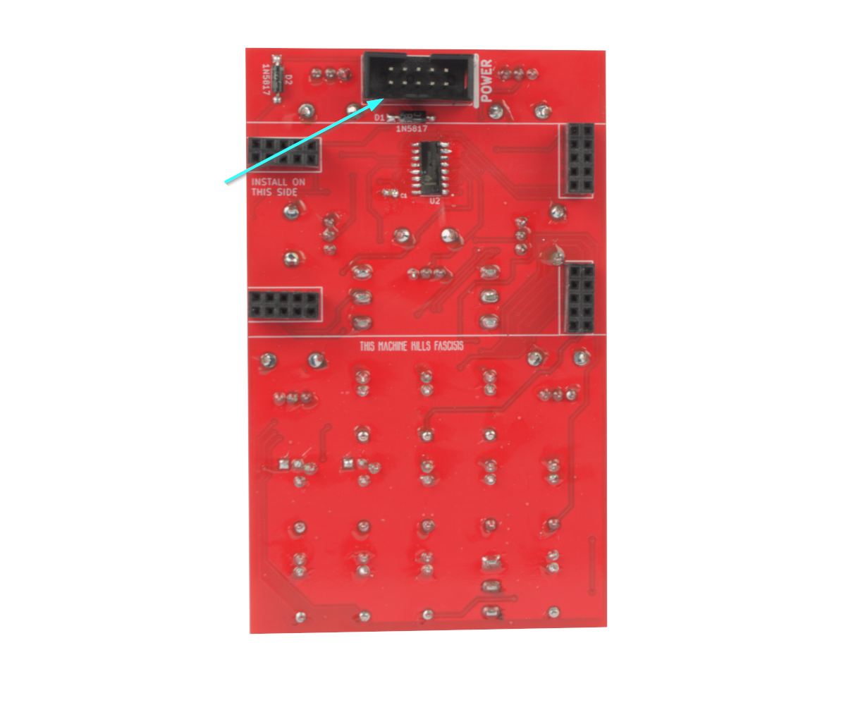
- Now solder the shrouded power header. Be sure that the notch matches the PCB.
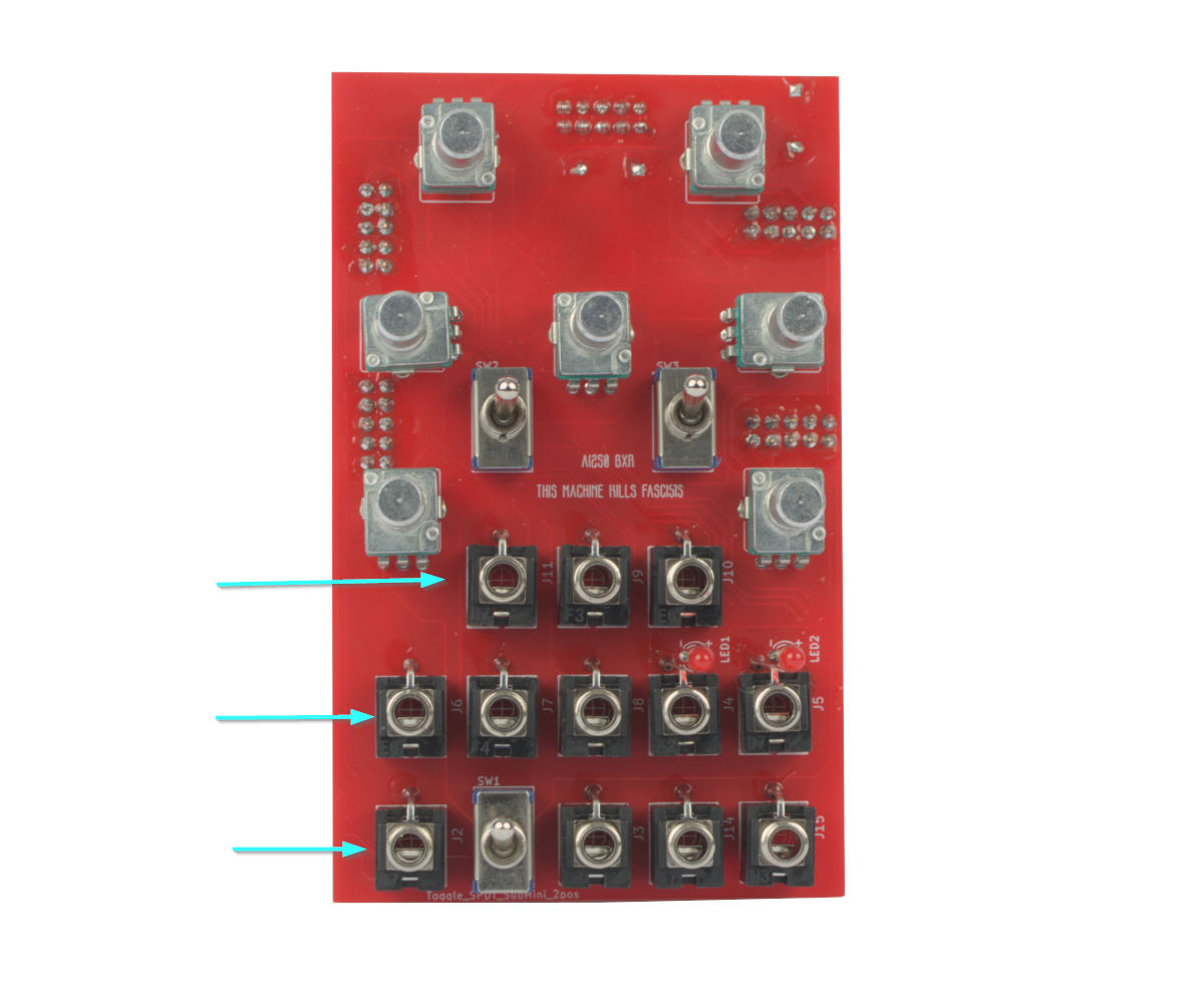
- Now solder the twelve jacks. I like to start with the bottom row and solder the ground lugs, then flip the board over and finish soldering them in.
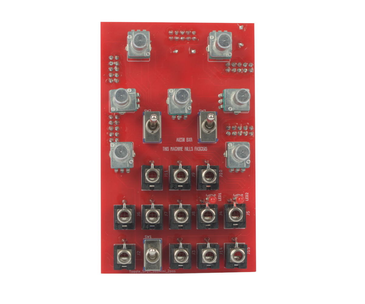
- BEFORE we solder the LED. This is a great time to put in all of the remaining parts: The LEDs, the switches, and the Potentiometers, and put the panel on. Then put a few nuts on the jacks to ensure all of the parts fit.
- Now We're done! Perform a Continuity Test and power on if there are no shorts between +, -, and GND.
- If you bought a kit, your daisy patch will be pre-programmed and tested, so you can just put it on. If not, to update it, grab the latest firmware here: https://github.com/AIsynthesis/ai250 and flash it using https://flash.daisy.audio/. Note that the Daisy Patch needs the module to be powered on in order to flash it.
How to Build the AI250 BXR
This is the build guide for the AI250 BXR
Table of Contents
- Resources
- About the AI250 BXR
- Tools Needed
- BOM (Bill of Materials)
- Build Guide
1. Resources
2. About the DIY BXR Eurorack Test Equipment Module.
The AI250 BXR is a eurorack module inspired by vintage nuclear test equipment. It can be used as an audio mangler, cv generator, and VCO. The BXR is a nod to vintage Boxcar Averagers, which were designed to acquire and analyze fast signals. The AI250 specifically replicates the real-time mathematical portion of a Boxcar Averager System, and processes audio or cv signals against either another signal or its internal v/o variable wave-shape VCO.
3. Tools Needed
- Soldering Iron: Cheap
- Solder
- Soldering Tip Cleaner
- SMD Tweezers
- Micro-Shear Flush Cutter
- Multimeter WITH Continuity Testing
4. BOM
| Category | Part | Quantity | Designation |
|---|---|---|---|
| Capacitor | .1uF Capacitor | 1 | C1 |
| Diode | 1N5817 Schottke Diode | 2 | D1-2 |
| Hardware | 2x5 Pin Socket | 4 | n/a |
| Hardware | Shrouded Power Header | 1 | Power |
| Hardware | Jack | 12 | J1-12 |
| IC | CD4051 | 1 | U2 |
| IC | Daisy Patch | 1 | n/a |
| LED | 3mm LED | 2 | LED 1-2 |
| Potentiometer | B10K Pot | 7 | Pot 1-7 |
| Nut | Nut | 12 | Switch | SPDT Switch | 3 | SW1-3 |
5. Build Guide
- To start, we need to solder the CD4051. Pin 1 is indicated by a white dot in the lower right corner. The chip I am using has a line, this should point downwards.
- Now solder the .1uF capacitor. Now we are done with SMD parts.
- Now solder the four 2x5 pin sockets. The trick I use, is to connect them to the Daisy seed and then connect them to the PCB and solder them in.
- Now solder the two 1N5817 Diodes. These will protect the module in case power is reversed. Just make sure the stripe on the diode matches the stripe on the PCB.
- Now solder the shrouded power header. Be sure that the notch matches the PCB.
- Now solder the twelve jacks. I like to start with the bottom row and solder the ground lugs, then flip the board over and finish soldering them in.
- BEFORE we solder the LED. This is a great time to put in all of the remaining parts: The LEDs, the switches, and the Potentiometers, and put the panel on. Then put a few nuts on the jacks to ensure all of the parts fit.
- Now We're done! Perform a Continuity Test and power on if there are no shorts between +, -, and GND.
- If you bought a kit, your daisy patch will be pre-programmed and tested, so you can just put it on. If not, to update it, grab the latest firmware here: https://github.com/AIsynthesis/ai250 and flash it using https://flash.daisy.audio/. Note that the Daisy Patch needs the module to be powered on in order to flash it.
How to Build the AI250 BXR
This is the build guide for the AI250 BXR
Table of Contents
- Resources
- About the AI250 BXR
- Tools Needed
- BOM (Bill of Materials)
- Build Guide
1. Resources
2. About the DIY BXR Eurorack Test Equipment Module.
The AI250 BXR is a eurorack module inspired by vintage nuclear test equipment. It can be used as an audio mangler, cv generator, and VCO. The BXR is a nod to vintage Boxcar Averagers, which were designed to acquire and analyze fast signals. The AI250 specifically replicates the real-time mathematical portion of a Boxcar Averager System, and processes audio or cv signals against either another signal or its internal v/o variable wave-shape VCO.
3. Tools Needed
- Soldering Iron: Cheap
- Solder
- Soldering Tip Cleaner
- SMD Tweezers
- Micro-Shear Flush Cutter
- Multimeter WITH Continuity Testing
4. BOM
| Category | Part | Quantity | Designation |
|---|---|---|---|
| Capacitor | .1uF Capacitor | 1 | C1 |
| Diode | 1N5817 Schottke Diode | 2 | D1-2 |
| Hardware | 2x5 Pin Socket | 4 | n/a |
| Hardware | Shrouded Power Header | 1 | Power |
| Hardware | Jack | 12 | J1-12 |
| IC | CD4051 | 1 | U2 |
| IC | Daisy Patch | 1 | n/a |
| LED | 3mm LED | 2 | LED 1-2 |
| Potentiometer | B10K Pot | 7 | Pot 1-7 |
| Nut | Nut | 12 | Switch | SPDT Switch | 3 | SW1-3 |
5. Build Guide
- To start, we need to solder the CD4051. Pin 1 is indicated by a white dot in the lower right corner. The chip I am using has a line, this should point downwards.
- Now solder the .1uF capacitor. Now we are done with SMD parts.
- Now solder the four 2x5 pin sockets. The trick I use, is to connect them to the Daisy seed and then connect them to the PCB and solder them in.
- Now solder the two 1N5817 Diodes. These will protect the module in case power is reversed. Just make sure the stripe on the diode matches the stripe on the PCB.
- Now solder the shrouded power header. Be sure that the notch matches the PCB.
- Now solder the twelve jacks. I like to start with the bottom row and solder the ground lugs, then flip the board over and finish soldering them in.
- BEFORE we solder the LED. This is a great time to put in all of the remaining parts: The LEDs, the switches, and the Potentiometers, and put the panel on. Then put a few nuts on the jacks to ensure all of the parts fit.
- Now We're done! Perform a Continuity Test and power on if there are no shorts between +, -, and GND.
- If you bought a kit, your daisy patch will be pre-programmed and tested, so you can just put it on. If not, to update it, grab the latest firmware here: https://github.com/AIsynthesis/ai250 and flash it using https://flash.daisy.audio/. Note that the Daisy Patch needs the module to be powered on in order to flash it.
How to Build the AI250 BXR
This is the build guide for the AI250 BXR
Table of Contents
- Resources
- About the AI250 BXR
- Tools Needed
- BOM (Bill of Materials)
- Build Guide
1. Resources
2. About the DIY BXR Eurorack Test Equipment Module.
The AI250 BXR is a eurorack module inspired by vintage nuclear test equipment. It can be used as an audio mangler, cv generator, and VCO. The BXR is a nod to vintage Boxcar Averagers, which were designed to acquire and analyze fast signals. The AI250 specifically replicates the real-time mathematical portion of a Boxcar Averager System, and processes audio or cv signals against either another signal or its internal v/o variable wave-shape VCO.
3. Tools Needed
- Soldering Iron: Cheap
- Solder
- Soldering Tip Cleaner
- SMD Tweezers
- Micro-Shear Flush Cutter
- Multimeter WITH Continuity Testing
4. BOM
| Category | Part | Quantity | Designation |
|---|---|---|---|
| Capacitor | .1uF Capacitor | 1 | C1 |
| Diode | 1N5817 Schottke Diode | 2 | D1-2 |
| Hardware | 2x5 Pin Socket | 4 | n/a |
| Hardware | Shrouded Power Header | 1 | Power |
| Hardware | Jack | 12 | J1-12 |
| IC | CD4051 | 1 | U2 |
| IC | Daisy Patch | 1 | n/a |
| LED | 3mm LED | 2 | LED 1-2 |
| Potentiometer | B10K Pot | 7 | Pot 1-7 |
| Nut | Nut | 12 | Switch | SPDT Switch | 3 | SW1-3 |
5. Build Guide
- To start, we need to solder the CD4051. Pin 1 is indicated by a white dot in the lower right corner. The chip I am using has a line, this should point downwards.
- Now solder the .1uF capacitor. Now we are done with SMD parts.
- Now solder the four 2x5 pin sockets. The trick I use, is to connect them to the Daisy seed and then connect them to the PCB and solder them in.
- Now solder the two 1N5817 Diodes. These will protect the module in case power is reversed. Just make sure the stripe on the diode matches the stripe on the PCB.
- Now solder the shrouded power header. Be sure that the notch matches the PCB.
- Now solder the twelve jacks. I like to start with the bottom row and solder the ground lugs, then flip the board over and finish soldering them in.
- BEFORE we solder the LED. This is a great time to put in all of the remaining parts: The LEDs, the switches, and the Potentiometers, and put the panel on. Then put a few nuts on the jacks to ensure all of the parts fit.
- Now We're done! Perform a Continuity Test and power on if there are no shorts between +, -, and GND.
- If you bought a kit, your daisy patch will be pre-programmed and tested, so you can just put it on. If not, to update it, grab the latest firmware here: https://github.com/AIsynthesis/ai250 and flash it using https://flash.daisy.audio/. Note that the Daisy Patch needs the module to be powered on in order to flash it.
Congratulations!
Share your build on Facebook and Instagram!
If you are having any issues at all, please contact me at: https://aisynthesis.com/contact/.