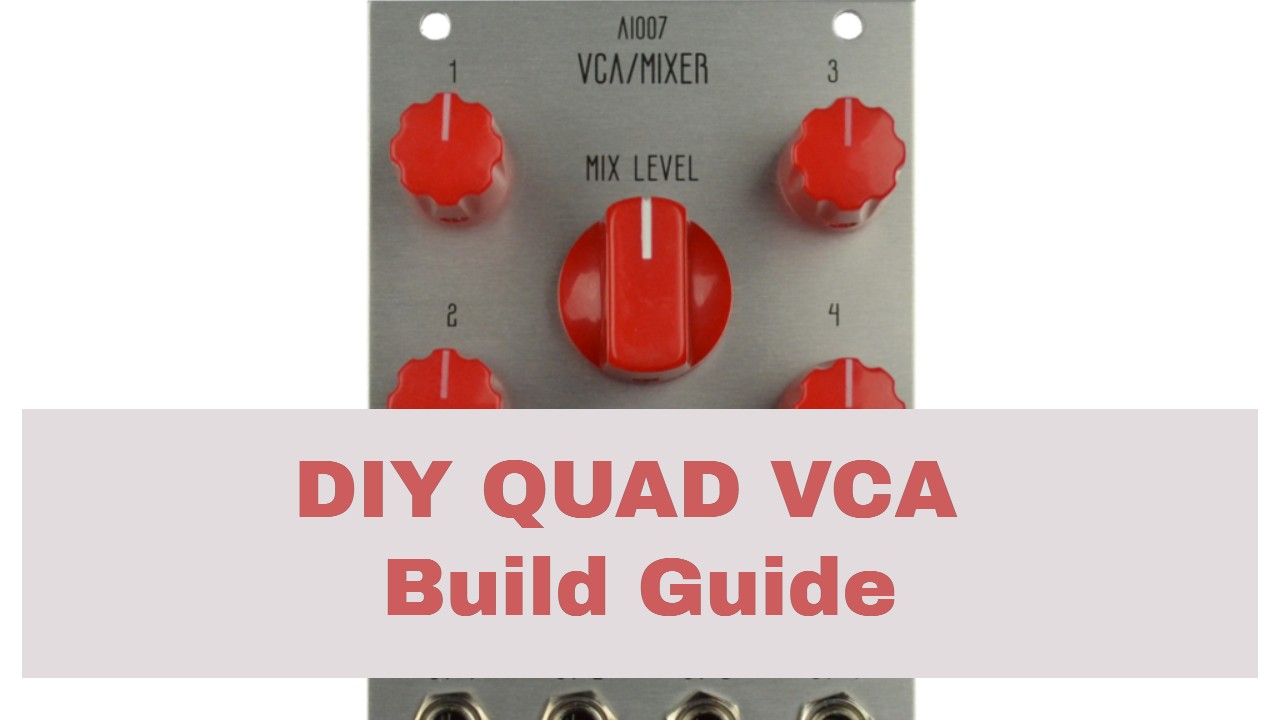
How to Build the AI007 Eurorack Quad VCA Mixer
This is the build guide for the AI007 Eurorack Quad VCA Mixer
Table of Contents
- Resources
- About the AI007 Eurorack Quad VCA Mixer
- Tools Needed
- BOM (Bill of Materials)
- Build Guide
1. Resources
2. About the AI007 Eurorack Quad VCA Mixer
The AI007 Eurorack Quad VCA Mixer is a compact, high quality, and flexible way to control voltage (audio or cv) in your modular system). Each of the four inputs are DC coupled, allowing the amplitude of CV signals as well as audio rate signals to be voltage controlled. The outputs are also normalled together into a mixer, allowing the AI007 Eurorack Quad VCA Mixer to be used as a voltage controlled mixer. Once a cable is patched into a VCA output that output is removed from the mixer signal, allowing each channel to be used independently, giving users four VCAs in total. In addition to being plentiful, the VCAs are also highly functional; a dedicated knob shapes the curve response from Linear to Exponential, while the CV control of each channel can accept audio rate modulation (giving one access to something similar to ring modulation).
The AI007 Eurorack Quad VCA Mixer project is advanced and not for beginners. In addition to using SMD parts, (805 and larger,) there are also a large number of thru hold components. Care must be taken to ensure there are no shorts, and if you use additional flux, you may need to probe for continuity in odd places.
3. Tools Needed
- Soldering Iron: Cheap
or Nice
- Solder
- Soldering Tip Cleaner
- Diagonal Cutters
- Precision Screwdriver Set
- SMD Tweezers
4. BOM
| Category | Part | Quantity | Designation |
|---|---|---|---|
| Capacitor (Electrolytic) | 10uF Capacitor | 2 | C1-2 |
| Capacitor | .1uF Capacitor | 4 | C3-6 |
| Capacitor | 470nF Capacitor | 4 | C7-10 |
| Capacitor | 47pF Capacitor | 2 | C31-32 |
| Capacitor | 47pF SMD Capacitor | 8 | C12, 14, 17, 19, 22, 24, 27, 29 |
| Capacitor | 560pF SMD Capacitor | 8 | C11, 15, 16, 20, 21, 25, 26, 30 |
| Capacitor | 100pF SMD Capacitor | 4 | C13, 18, 23, 28 |
| Diode | BAT85 Diode or 1N5819 | 2 | D1, 2 |
| Hardware | 8 Pin IC Socket | 1 | U3 |
| Hardware | Power Header | 1 | Power |
| Hardware | 4 Pin Female Header | 8 | J2, 4, 6, 8, 10, 12, 14, 16 |
| Hardware | 4 Pin Male Header | 8 | J1, 3, 5, 7, 9, 11, 13, 15 |
| Hardware | Jack | 13 | MO, O1, O2, O3, O4, AIN1, AIN2, AIN3, AIN4, CV1, CV2, CV3, CV4 |
| Hardware | Nut | 13 | |
| IC | SMD SOIC-14 TL074 | 4 | U1, 2, 4, 5 |
| IC | SSM2164 | 2 | IC3, 4 |
| IC | TL072 | 1 | U3 |
| IC | LM4040C10 | 1 | IC1 |
| IC | LM4040C25 | 1 | IC2 |
| LED | Bi Polar LEDs | 4 | L1-4 |
| Potentiometer | B10K Tall Trimmer | 4 | Log/LIN1-4 |
| Potentiometer | B10K 9mm Alpha Potentiometer (or more tall trimmers) | 4 | CVIN1-4 |
| Potentiometer | A100K 9mm Alpha Potentiometer | 1 | Mix |
| Resistor | 10R OR 1n5817 Diode | 2 | R1, 2 |
| Resistor | 3.6K | 1 | R3 |
| Resistor | 2K | 1 | R4 |
| Resistor | 100K | 14 | R5, 16, 20, 31, 35, 46, 50, 58, 65, 61, 67, 68, 69, 70 |
| Resistor | 20M | 4 | R15, 30, 45, 60 |
| Resistor | 91K - 92K You can use 100k, but it won't be my "preferred" lin/log control | 4 | R32, 77, 81, 82 |
| Resistor | 330 Ohm | 1 | R71 |
| Resistor | 12K | 1 | R80 |
| Resistor, SMD | 5.1K | 8 | R8-9, 23-24, 38-39, 53-54 |
| Resistor, SMD | 1.2K | 4 | R11, 26, 41, 56 |
| Resistor, SMD | 100K | 12 | R7, 10, 12, 22, 25, 27, 37, 40, 42, 52, 55, 57 |
| Resistor, SMD | 49.9K | 4 | R73, 75, 87, 90 |
| Resistor, SMD | 510 Ohm | 16 | R6, 13, 14, 18, 21, 28, 29, 33, 36, 43, 44, 48, 51, 59, 63, 66 |
5. Build Guide
This is an advanced build! Support is limited. Take care and take breaks!
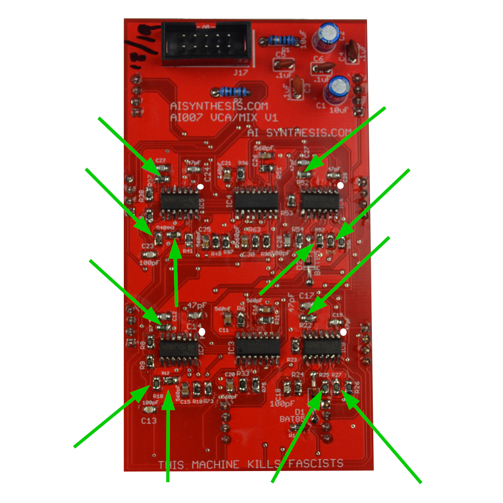
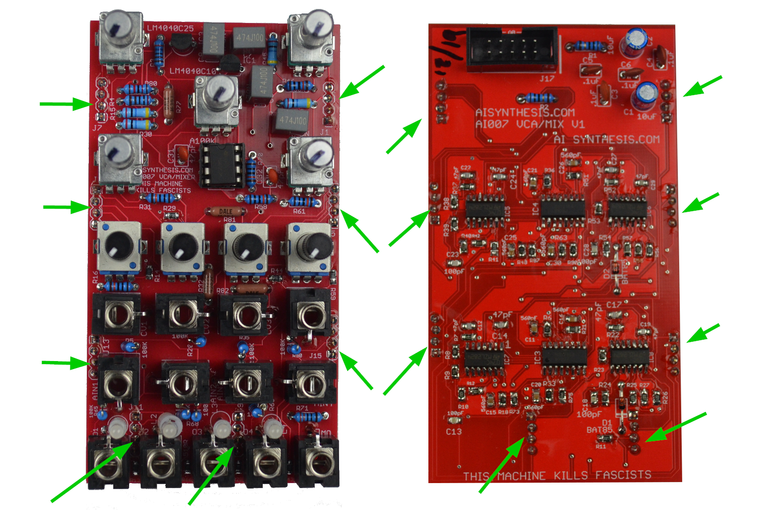
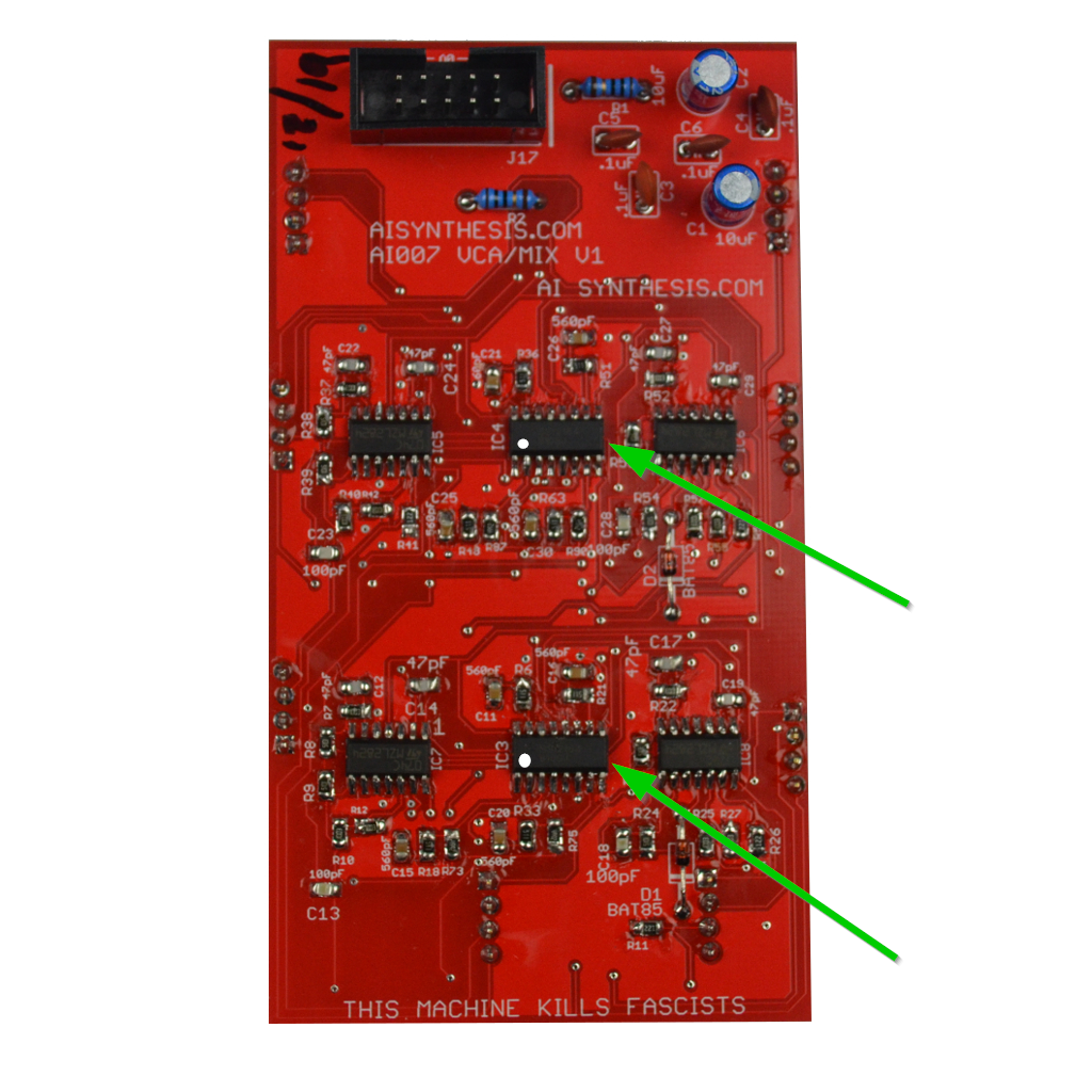 First, gather your parts together, and start with the 2164 ICs the image above shows white dots to help you align the ICs on the PCB. I like to tack down one pin and then solder the rest. I prefer to hand solder with leaded solder and no added flux (outside what is in the solder) as flux is conductive and can cause shorts. Watch the video if you have questions.
- Now place and solder the four TL074 ICs. In the image above I use white dots to help you find pin 1.
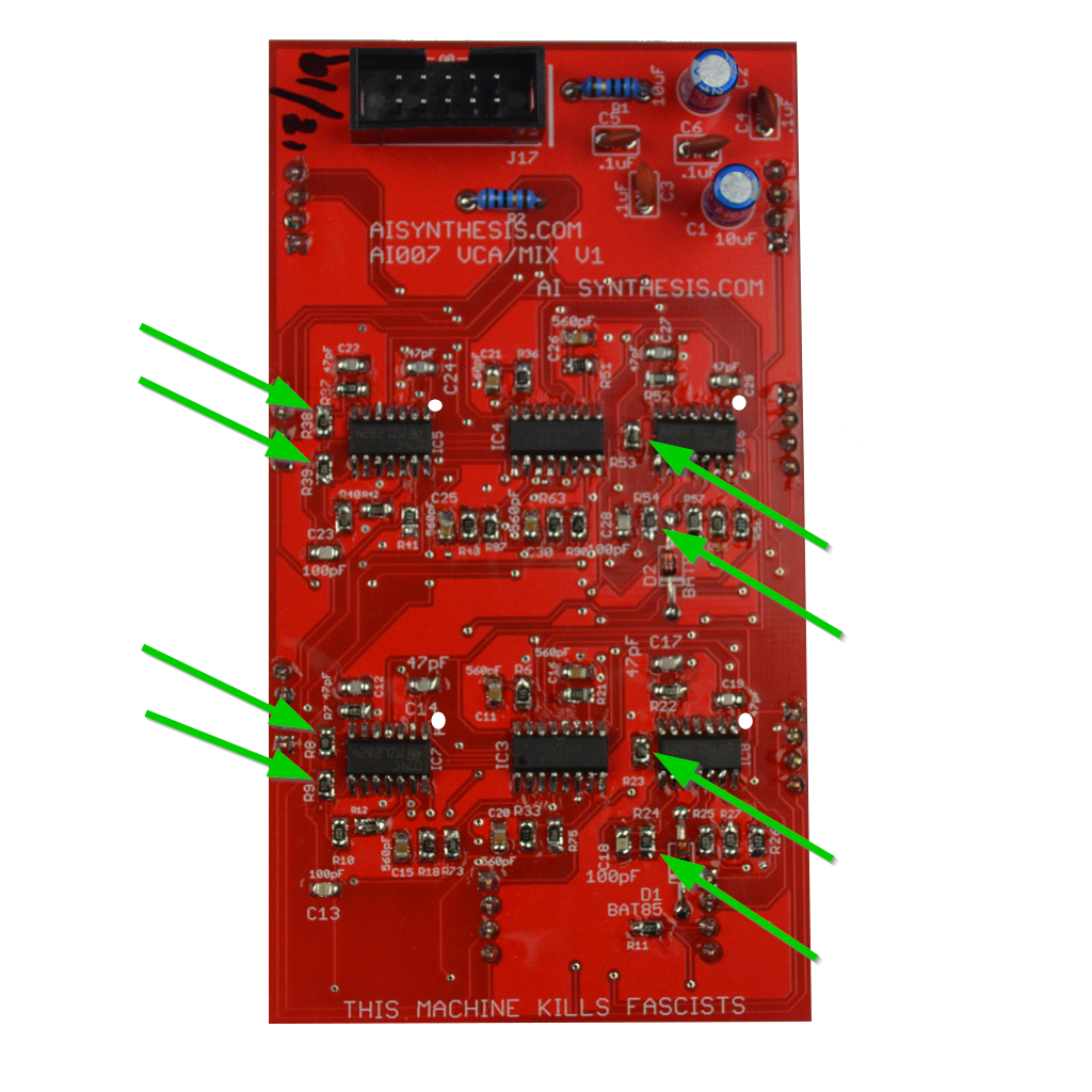
- Solder the eight 5.1K resistors. Again, I start with one pin, then solder the other side using tweezers to ensure the resistor doesn't "pop" up.
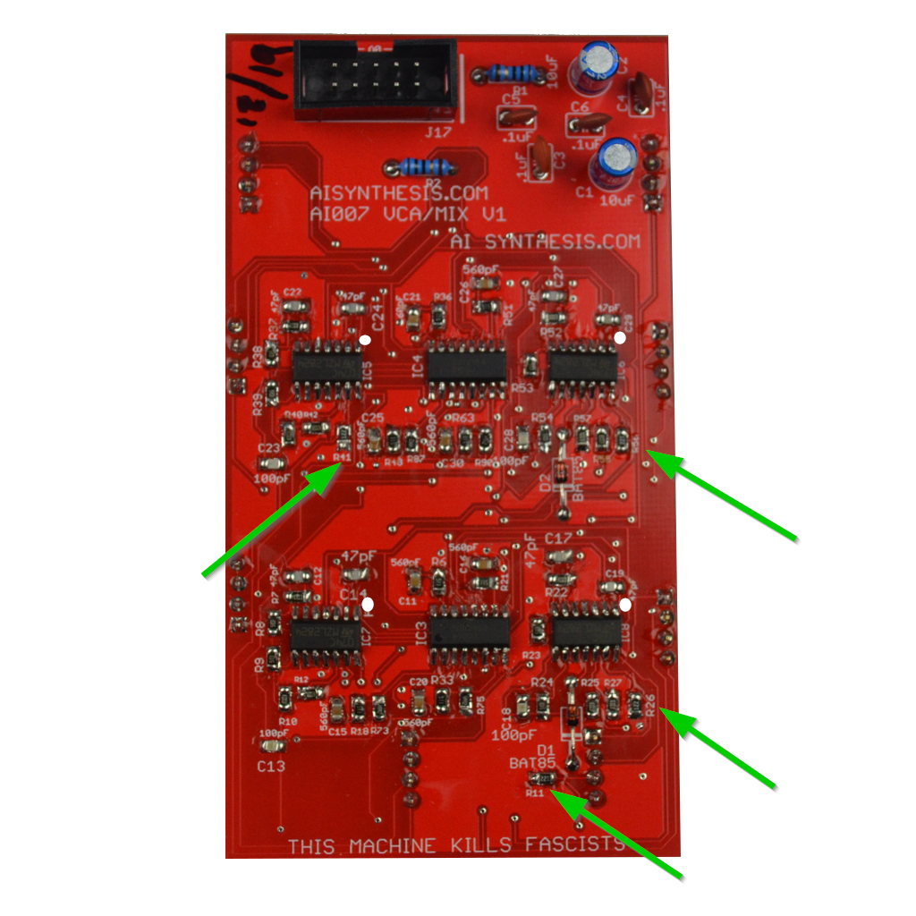
- Now place and solder the four 1.2K resistors.
- Then solder the twelve 100k Resistors.
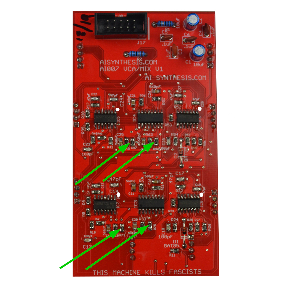
- At this point we move on to the 4 49.9K resistors.
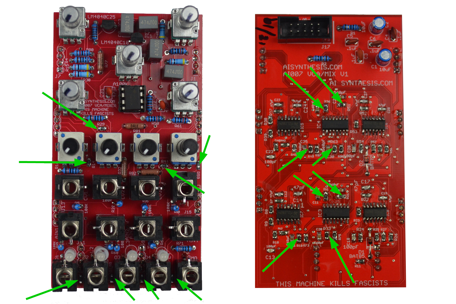
- There are 16 510 Ohm Resistors. 8 of them are on the Panel-facing PCB.
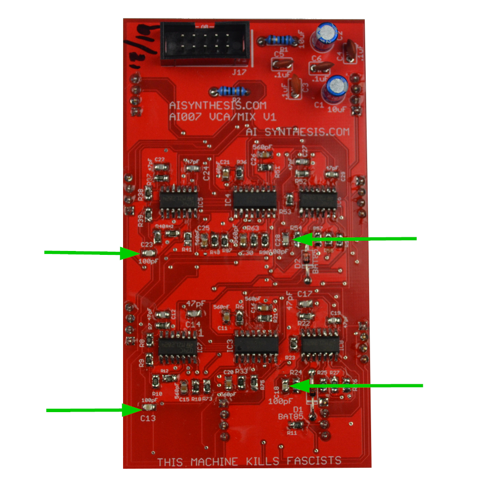
- Now solder the 4 100pF capacitors.

- Now solder the 8 47pF Capacitors.
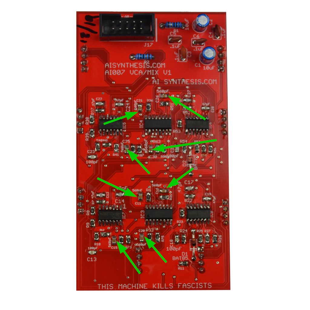
- Now solder the 8 560pF Capacitors. We're done with the SMD work!
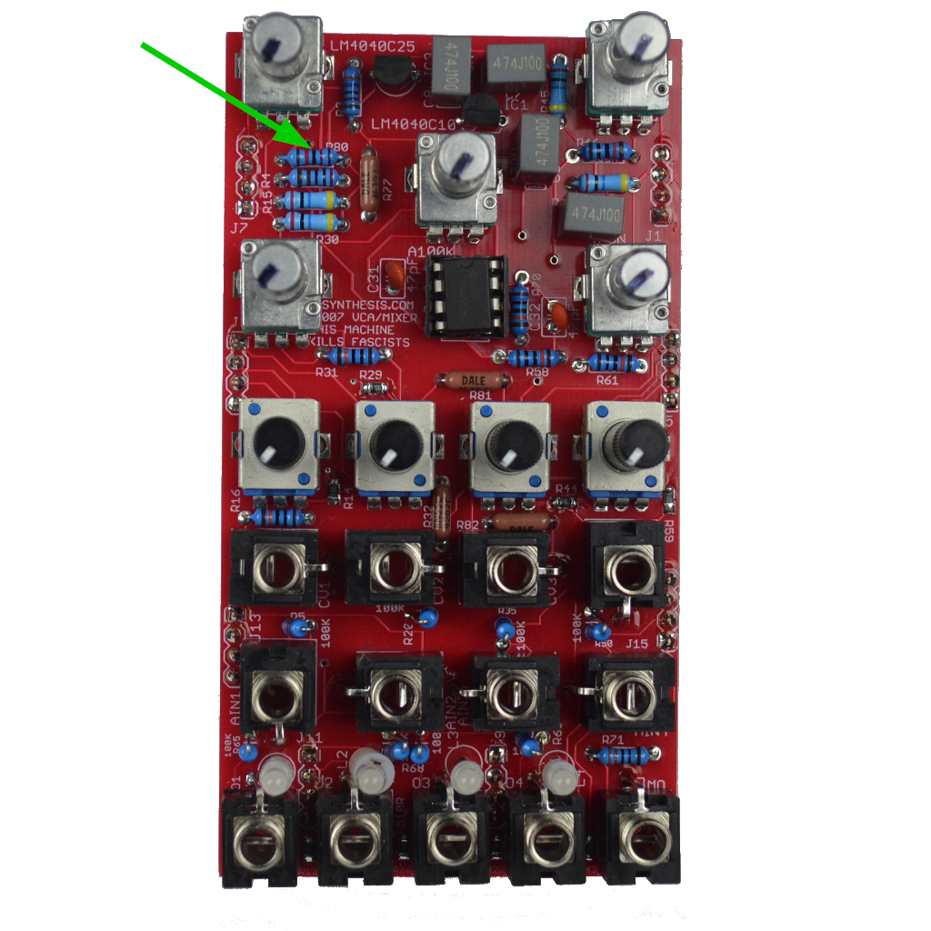
- Now solder the single 12K resistor.

- Now solder the single 2K resistor.

- Now solder the single 3.6K resistor.
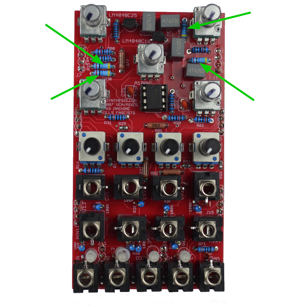
- Now solder the four 20M resistors.
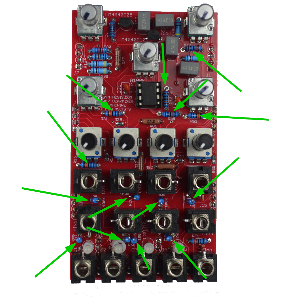
- Now move on to the fourteen 100k Resistors. Pay attention to ensure that the standing resistors are aligned so that the "exposed leg" doesn't risk shorting against any other part.
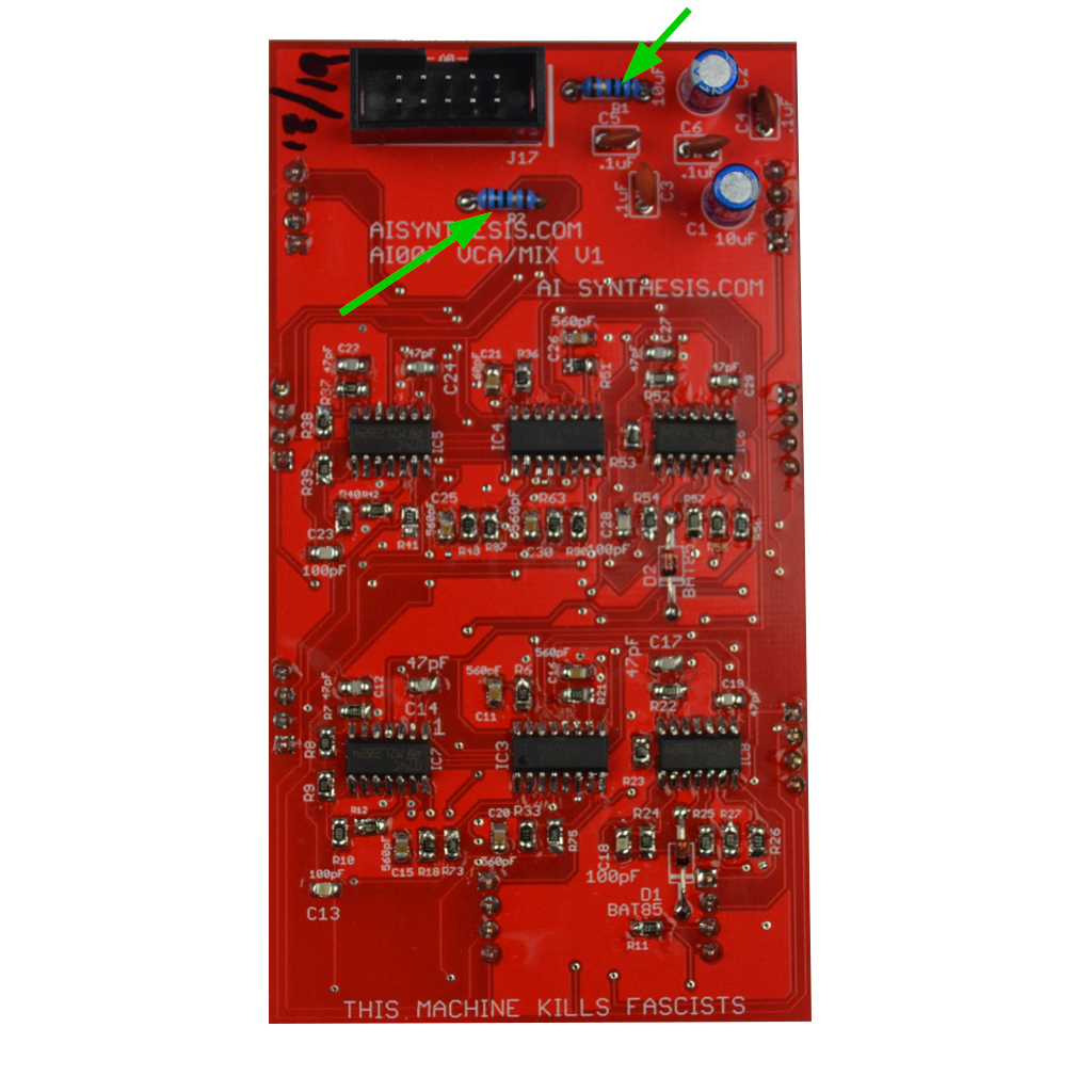
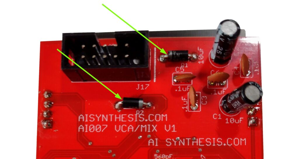
- Now move on to the two 10 ohm Resistors OR 1N5817 Diodes at R1 and R2. Your kit may have either part, and both are fine. The kits are transitioning to using 1N5817 Diodes instead of 10 Ohm resistors for further reverse power protection. The 10 Ohm resistors are not polarized and have no orientation. The 1n5817 Diodes must be put in the correct orientation, shown below. When I re-order PCBs they will have the orientation on the PCB. I didn’t want to throw out a bunch of otherwise good PCBs.
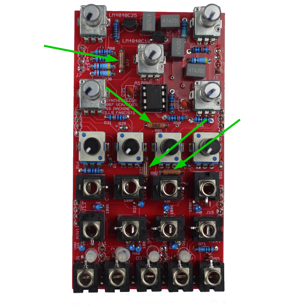
- Now move on to the four 91K-92K Resistors. 92K is mathematically better, but hard to find. 91K works just as well.
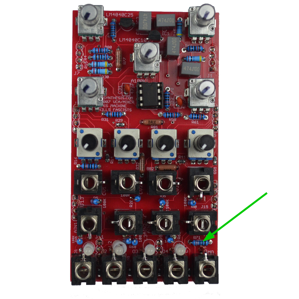
- Now move on to the single 330 ohm resistors.
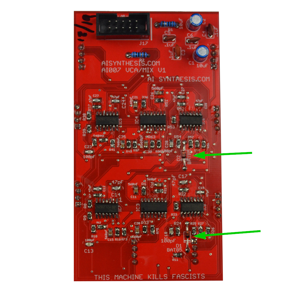
- Now move on to the two Bat85 diodes. These are polarized and the black lines should line up with the white line on the PCB silkscreen.
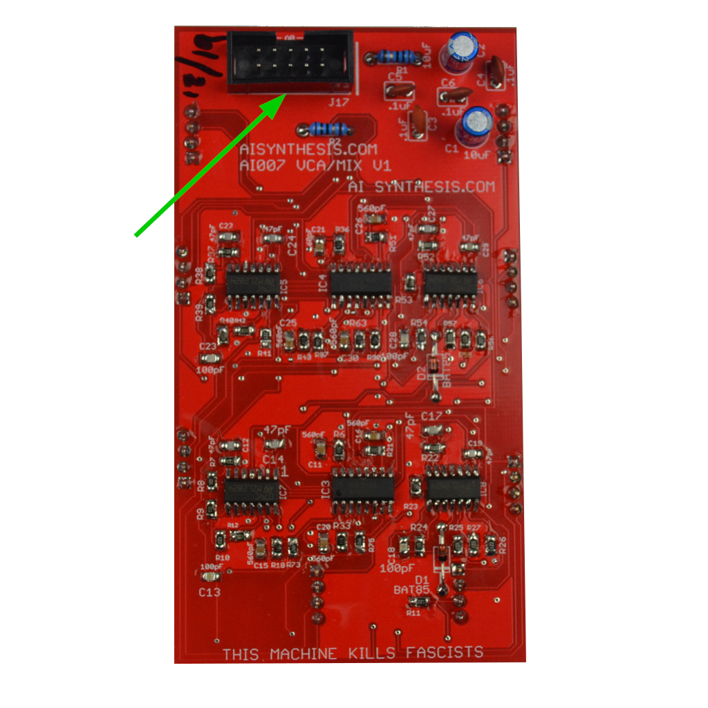
- Now move on to the shrouded power header. Mind the orientation.
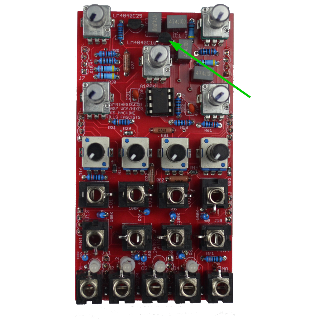
- Now move on to the LM4040C10. Don't get it confused with the C25, and ensure that the orientation is correct.

- Now move on to the LM4040C25. Ensure that the orientation is correct.
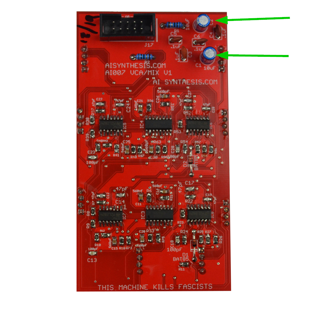
- Now move on to the 10uF capacitors. Ensure that the polarity is correct.
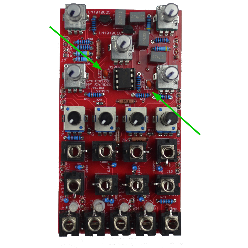
- Now move on to the two 47pF capacitors.
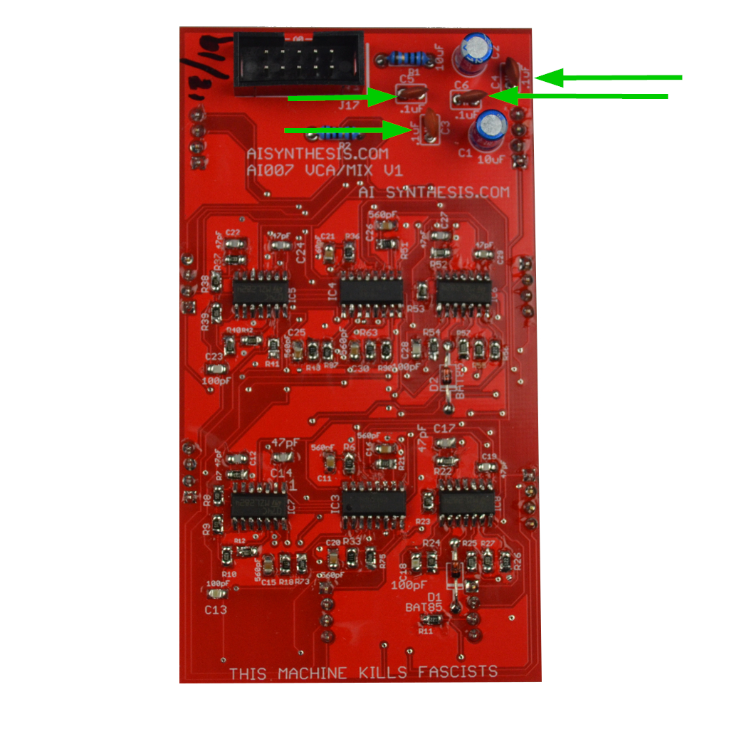
- Now move on to the four .1uF capacitors.
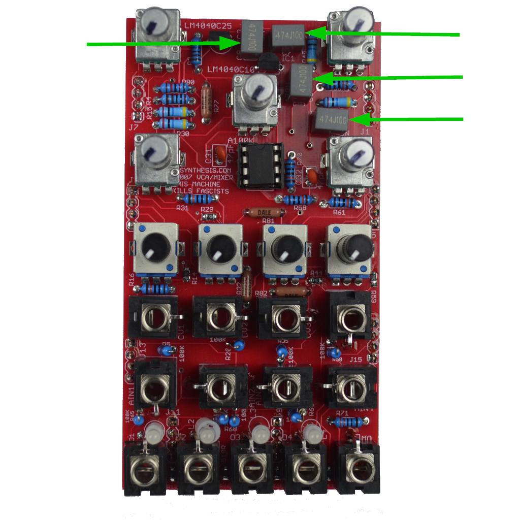
- Now move on to the four 470nF capacitors. Ensure that they rest as flat as possible to the PCB, as they are fairly tall, and we don't want them to adjust the way the panel rests.
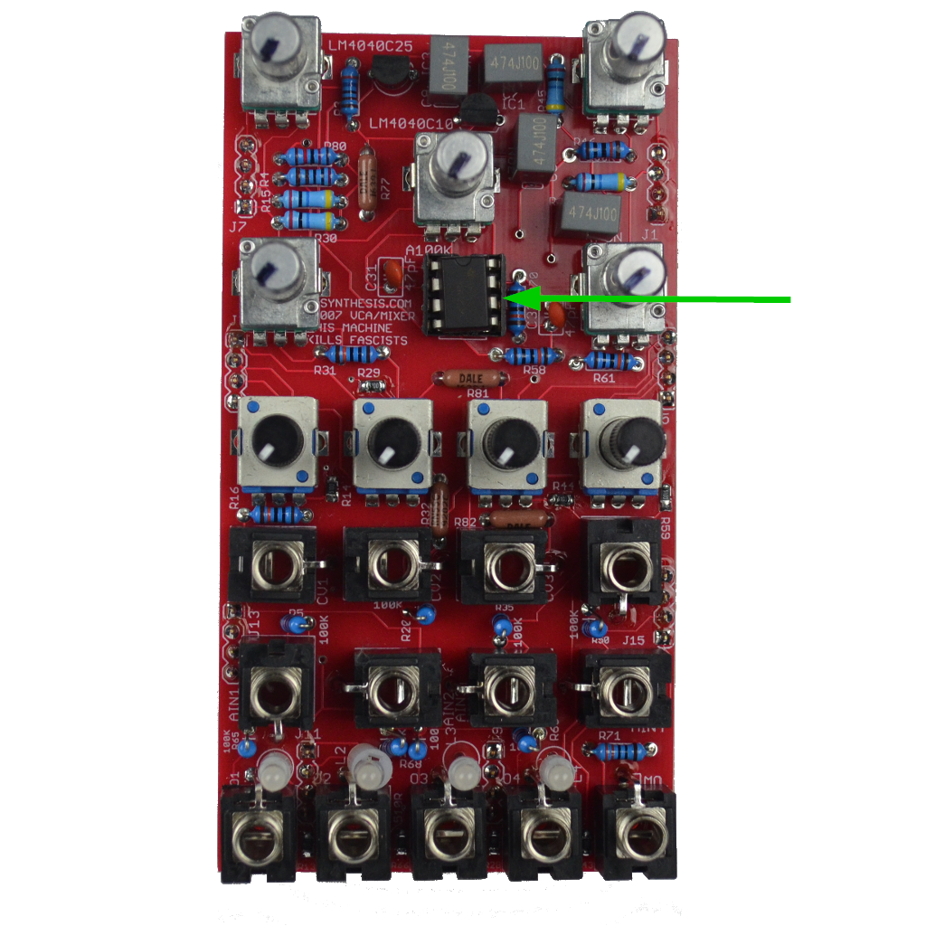
- Now move on to the TL072 and socket. Ensure the polarity of the TL072 is correct.
- Now move on to the 16 four pin headers. I prefer to keep the "male" headers on one PCB and the "female" ones on the other. I prefer to fit the pcbs together with the headers in prior to soldering. Watch the video if you have any questions.
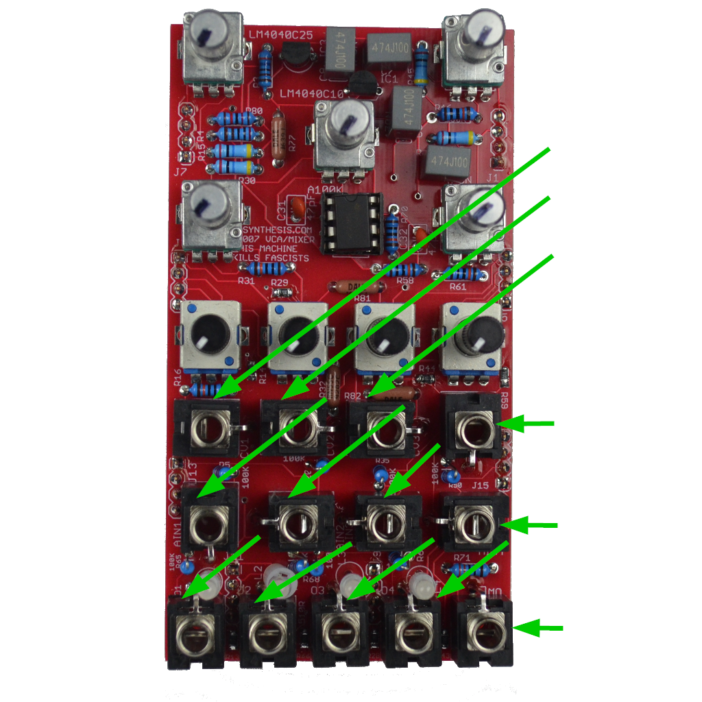
- Now place the thirteen jacks. I like to solder in the ground lugs (the lugs that stick out) from the top of the PCB, and then wait to solder the rest of the pads until I've finished placing the pots, trimmers, and LEDs with the panel intact.
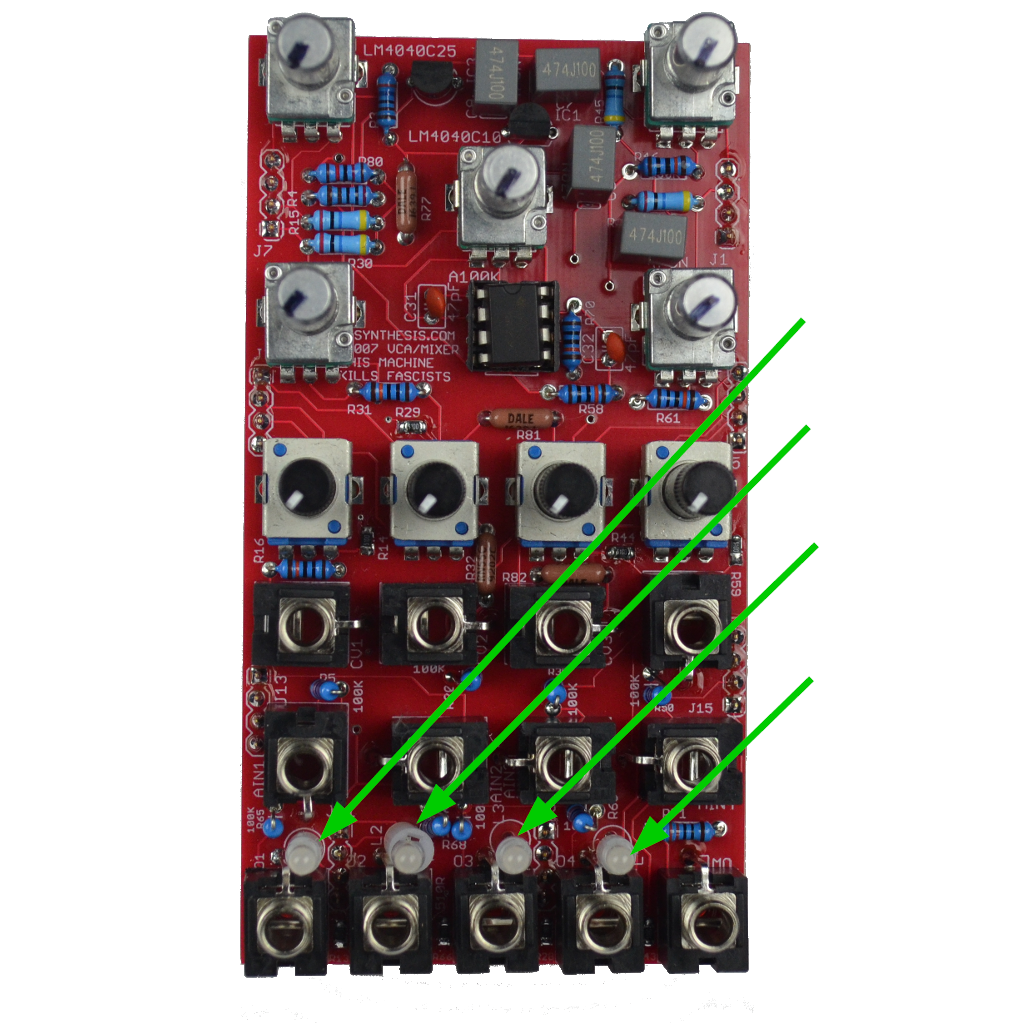
- Now move on to the four bi-color leds. You may want to wait until soldering until you fit the panel on, as I like to fit them as far out as they go through the panel. the long leg should be 'up."
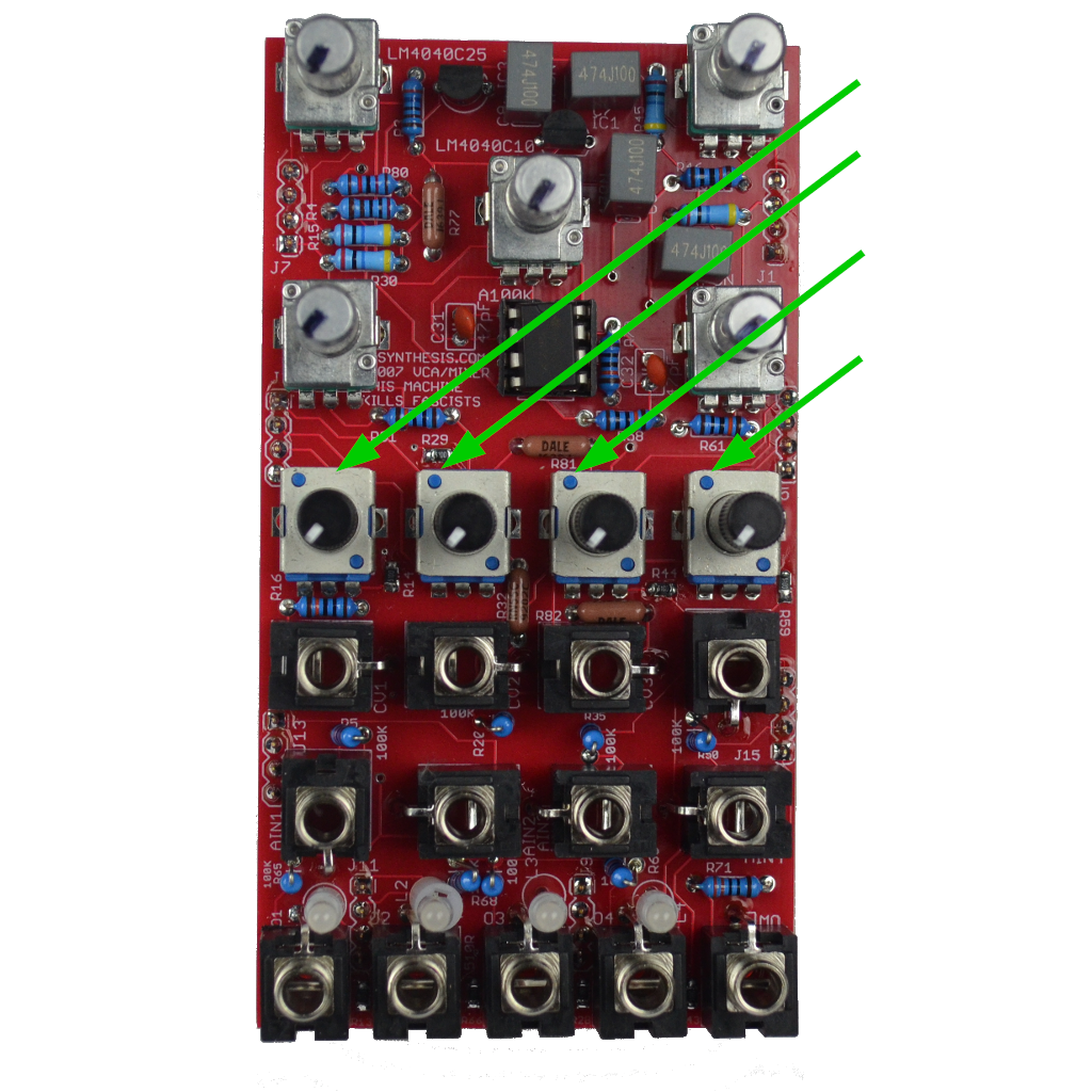
- Now move on to the four tall trimmers. You might want to wait until the panel is fitted to solder them in.
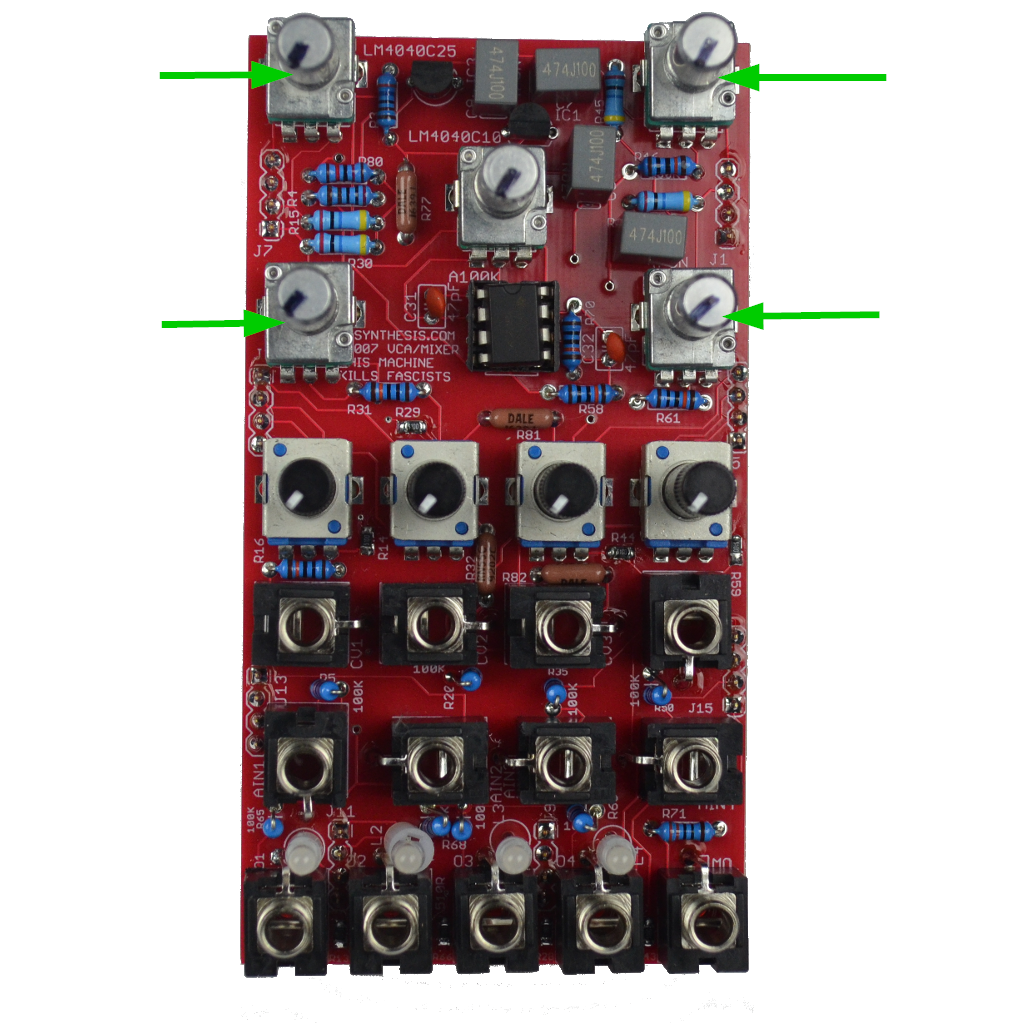
- Now move on to the four B10K Pots. You might want to wait until the panel is fitted to solder them in.
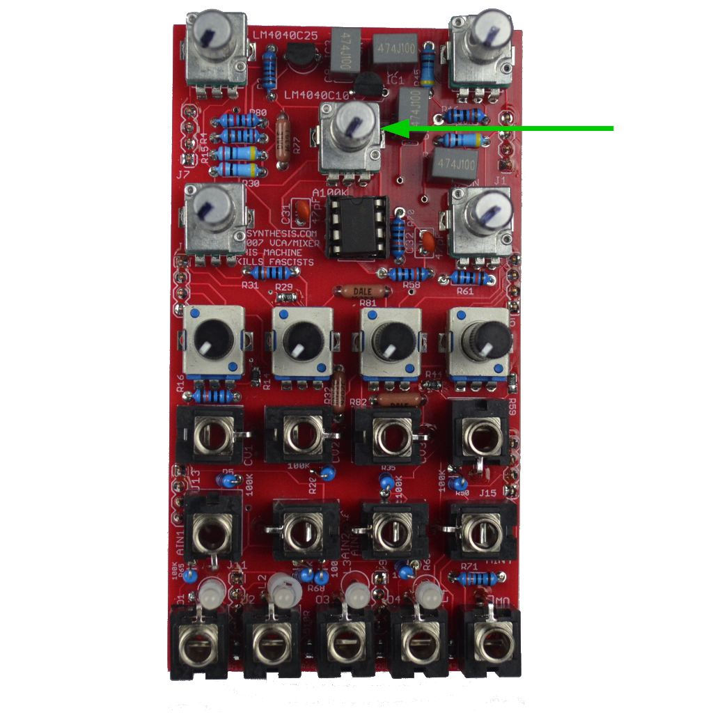
- Now move on to the single A100K Pot. You might want to wait until the panel is fitted to solder them in.
- With everything installed, perform a continuity test and if all looks good. Power on.
- If one channel is wonky, find the parts of that channel in the schematic and reflow.
- Share your build on Facebook and Instagram!
- If you are having any issues at all, please contact me at: https://aisynthesis.com/contact/.